


M051-00K58-A035
Service Kit Instructions
How To…Install Switch Bracket Assembly on Next Generation Treadmills
Installation Kit M051-00K58-A035 consists of a Switch Bracket Assembly and Hardware. Proceed with the
following steps to facilitate proper installation.
1. Verify that the treadmill is at 0% incline.
2. Turn the power off and unplug the unit from the
electrical outlet.
3. Remove the four SCREWS securing the MOTOR
COVER to the FRAME. Remove the MOTOR
COVER.
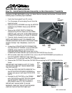
4. Remove the HOME SWITCH CABLE by
disconnecting the two leads from the HOME
SWITCH and unplug the 4-PIN HOME SWITCH
CONNECTOR from the LIFT/WAX PC BOARD.
5. Carefully tip the treadmill onto its right side.
NOTE: BE CAREFUL NOT TO DAMAGE THE
FRAME SURFACE OR PLASTIC ACCESS PANEL
WHEN TIPPING THE TREADMILL ONTO ITS
SIDE.
6. Unplug the 4-PIN ACTUATOR CONNECTOR
from the WAX/LIFT BOARD, remove GROUND
SCREW, which attaches the ACTUATOR
GROUND WIRE (Green with yellow strip) to the
POWER BOX ENCLOSURE, and remove the ACTUATOR from the unit.
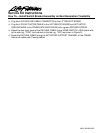
7. With a marker make two coincident lines; one on the ACTUATOR BASE and another on
THE ACTUATOR TUBE-NUT (see Figure 2).
8. Remove 9/16” nut and bolt from the LIFT ARM WELDMENT.
9. Remove the COTTER PIN and the CLEVIS PIN connecting the ACTUATOR pivot to the
frame.
IMPORTANT: BE CAREFUL NOT TO TURN
ACTUATOR TUBE-NUT WHILE REMOVING
THE ACTUATOR.
10. Place the DECLINE SWITCH BRACKET on
the ACTUATOR EXTENDED SCREWS as
shown and secure it with two #10-24 LOCK
NUTS.
11. Reinstall the ACTUATOR on the FRAME
with CLEVIS PIN and COTTER PIN. Attach
the ACTUATOR TUBE-NUT to the LIFT
WELDMENT with 9/16” NUT and BOLT.
IMPORTANT: MAKE SURE TO ALIGN
MARKED LINES ON THE ACTUATOR BASE
AND ON THE ACTUATOR TUBE-NUT.
Home
Switch
Home
Switch
Cable
Lift / Wax
PC Board
4-Pin
Home Switch
Connector
Figure 1
Decline
Switch
Bracket
Actuator
Base
Actuator
Tube-Nut
Marked
Lines
Extended
Screw
#10-24
Lock Nut
Black
Wire
Red
Wire
Figure 2