1© COPYRIGHT 2004 LUX PRODUCTS CORPORATION. ALL RIGHTS RESERVED
LUX PRODUCTS CORPORATION • Mt. Laurel, New Jersey 08054, USA 43368
IMPORTANT!
Please read all instructions carefully before
beginning installation and save for future reference.
Before removing any wiring from your existing thermostat, its wires
must be labeled with their terminal designations.
Ignore the color of the wires since they may not comply with any standard.
Thank you for your confidence in our product. To obtain the best results from
your investment, please read this manual and acquaint yourself with your
purchase before installing your new thermostat. Then follow the installation
procedures, one step at a time. This will save you time and minimize the chance
of damaging the thermostat and the systems it controls. These instructions may
contain information beyond that required for your particular installation. Please
save for future reference.
PSDH121 SERIES
DIGITAL ELECTRONIC HEAT PUMP THERMOSTAT
Set TemperatureChoose Heat or Cool
Installs Easily
Easy as
1–2–3
Complete, Easy To Read
INSTALLATION AND OPERATING INSTRUCTIONS
COMPATIBILITY
LUX PSDH121 was designed
for use with single stage heat
pump systems with auxiliary
and/or emergency heat. These
systems are typical known as
2-stage heat one stage cool heat
pump systems.
FEATURES
●
Slim design may be vertically or horizontally
mounted
●
Large easy to read backlit display
●
Fan switch for system or continuous fan
operation
●
Emergency Heat Switch
●
Simple temperature Up or Down keys will
display and adjust the Set Temperature.
●
Temperature displays in F° or C°
●
Temperature differential SWING settings of
0.25 and 0.5
●
Selectable 2 or 5-Minute Minimum Run/Off time provides short cycle and
compressor protection
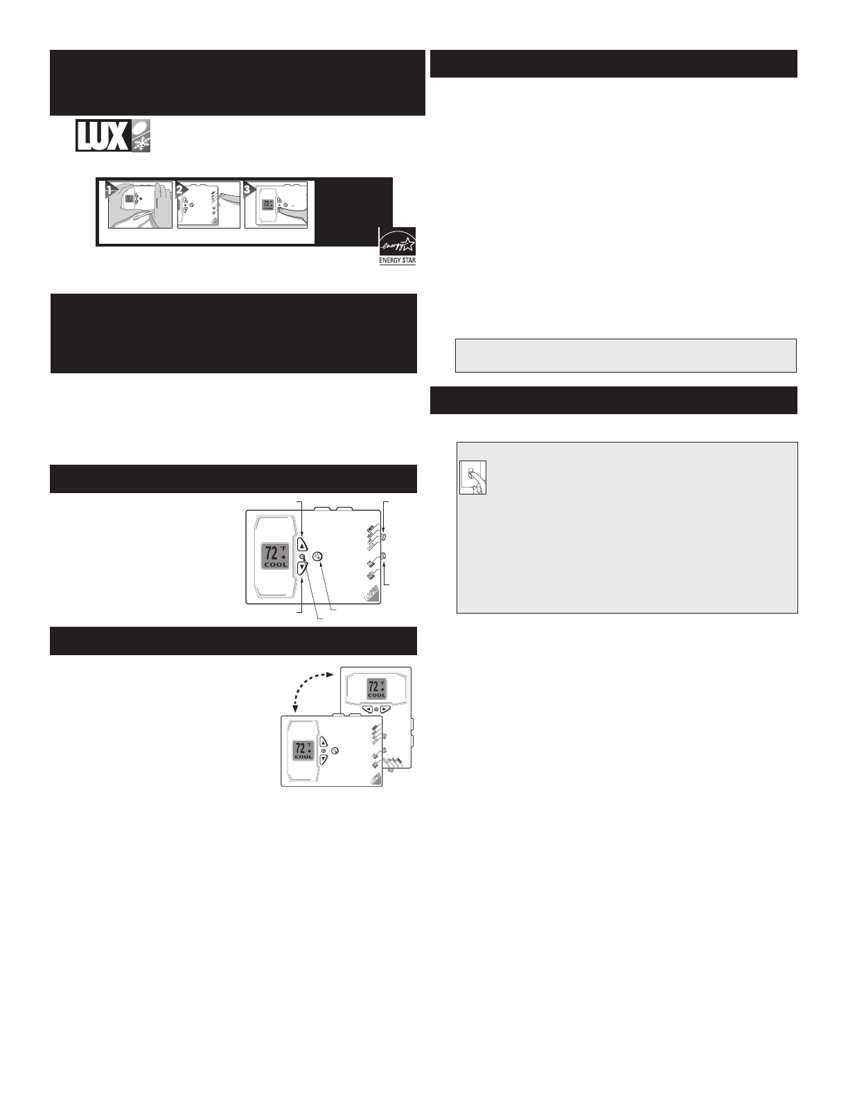
TEMP UP MODE
FAN
MODE
TEMP DOWN
BACKLIGHT
RESET
WARNING: Use Energizer
®
or DURACELL
®
Alkaline Batteries Only.
Energizer
®
is a registered trademark of Eveready Battery Company, Inc.
DURACELL
®
is a registered trademark of The Gillette Company, Inc.
●
In the winter, set the system switch to HEAT to control your system while
heating.
●
In the summer, set the switch to COOL to control your system while cooling.
●
Press the TEMPERATURE UP or DOWN key in order to show the
current SET TEMPERATURE.
●
Press TEMPERATURE UP or DOWN keys again until your desired
temperature is displayed. The display will show the current room temperature
again after two seconds.
●
Press the light bulb button to illuminate the display. Adjusting the temperature
will keep the display lit until no button has been pressed for over ten seconds.
●
In spring and fall or when windows are open, you can set the system switch
to OFF.
●
Setting the FAN switch to AUTO automatically runs your system’s fan during
heating and cooling.
●
Setting the FAN switch to ON runs your system’s fan continuously even
without heating or cooling.
●
Setting the Mode switch to EMER (emergency heat) runs your Emergency
heating system rather than the heat pump.
NOTE
The FAN switch works only if your system provides a wire for a thermostat’s “G” terminal.
INSTALLATION
Please read all instructions carefully before beginning installation.
CAUTION
*** Turn off electricity to the appliance before installing or
servicing thermostat or any part of the system. Do not turn
electricity back on until work is completed. ***
●
Do not short (jumper) across electric terminals at control on furnace or air
conditioner to test the system. This will damage the thermostat and void
your warranty.
●
All wiring must conform to local codes and ordinances.
●
This thermostat is designed for use with 24 volt systems. The thermostat
should be limited to a maximum of 1.5 amps; higher current may cause
damage to the thermostat. If you are in doubt, call your HVAC contractor.
●
Your thermostat is a precision instrument. Please handle it with care.
O
FF
TOOLS REQUIRED
●
#1 Phillips screwdriver (small)
●
Drill with 3/16-in. (4.8mm) bit
●
Wire stripper/cutter
THERMOSTAT LOCATION
On replacement installations, mount the new thermostat in place of the old
one unless the conditions listed below suggest otherwise. On new installations,
follow the guidelines listed below.
●
Remember that your PSDH121 may be mounted vertically or horizontally
when determining the optimal location.
●
Locate the thermostat on an inside wall, about 5 ft. (1.5m) above the floor,
and in a room that is used often.
●
Do not install it where there are unusual heating conditions, such as: in direct
sunlight; near a lamp, radio, television, radiator, register, or fireplace; near hot
water pipes in a wall; near a stove on the other side of a wall.
●
Do not locate in unusual cooling conditions, such as: on a wall separating an
unheated room; or in a draft from a stairwell, door, or window.
●
Do not locate in a damp area. This can lead to corrosion that will shorten
thermostat life.
●
Do not locate where air circulation is poor, such as: in a corner or an alcove;
or behind an open door.
●
Do not install the unit until all construction work and painting has been
completed.
OPERATING INSTRUCTIONS


