


1 2 3
SSIM-T5-04 Token Ring
SmartStack Interface Module
Introduction
The SmartStack SSIM-T5-04 provides four additional Token
Ring ports for the base SmartStack STS16-20RM or STS16-
20FRM Token Ring switch. These ports can be configured just
like the 20 fixed Token Ring ports on the base switch. Each or
all of the interface module ports can be configured (in
combination with any of the fixed ports on the base switch) to
be used in CrossLink connections, and configured to be
included in virtual LANs. The interface module ports support
address filters and BOOTP/TFTP, Telnet or SNMP sessions.
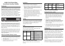
Figure 1. SSIM-T5-04 interface module Front Panel
The ports on the SSIM-T5-04 interface module support Token
Ring twisted-pair (UTP/STP) media via RJ-45 connectors.
The interface module ports can be configured just like the base
switch ports to provide either shared (half-duplex) 4 or 16
Mbps Token Ring connections or dedicated (full-duplex) 32
Mbps connections.
In addition to the RJ-45 Token-Ring connectors, there are 10
LEDs on the faceplate of the interface module (a set of two for
each port plus two for the interface module general status).
These LEDs indicate the operational status of the interface
module and of the ports.
SSIM-T5-04 Module Package Contents
The interface module package contains the following items:
•
One SSIM-T5-04 SmartStack interface module for the
Token Ring Switch
•
One SSIM-T5-04 SmartStack Interface Module
Installation Guide (this document)
Installation
1. Power off the base switch by unplugging it.
2. Remove the plate covering the expansion slot on the front
of the base switch by unscrewing the two retaining
thumbscrews. Keep the plate for use in the event that the
interface module is removed.
3. Carefully insert the interface module into the rails on each
side of the expansion slot, sliding it back until the
connector on the interface module is seated into the
connector at the back of the slot.When the interface
module is fully seated, the interface module faceplate will
be flush with the front of the base switch.
4. Secure the interface module with the two attached
thumbscrews.
Cabling
For specifications and directions about cabling the UTP/STP
universal expansion modules, see Appendix B in
SmartStack
STS16-20RM/STS16-20FRM Token Ring Switches,
Installation and User Guide
.
LEDs
The interface module has 10 LEDs.
Table 1 lists the two status LEDs on the left front of the
interface module and their meanings.
Table 1. Status LEDs and their meanings
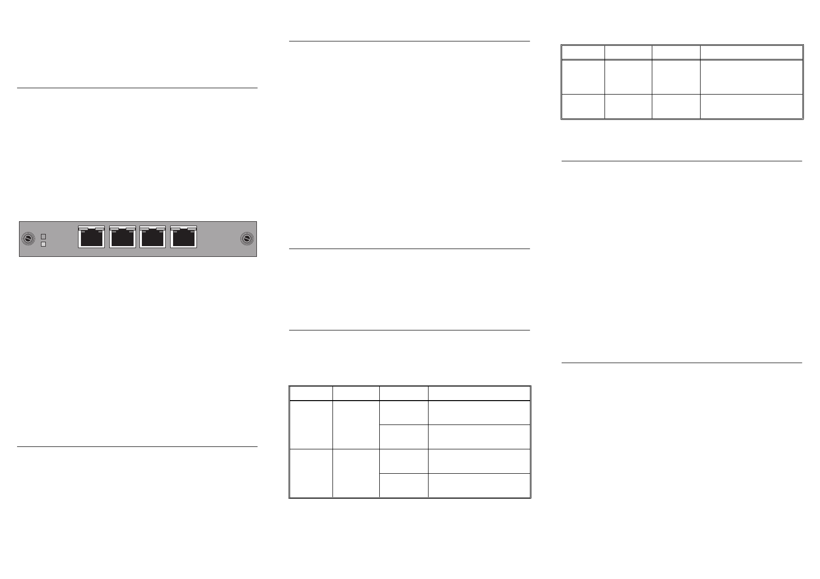
Table 2 lists the port LEDs above each RJ-45 and their
meanings.
Table 2. Port LEDs and their Meanings
Testing the interface module
1. Power on the base switch to start diagnostics. The STS16-
20RM Token Ring switch indicates that diagnostics are in
progress by turning on its DIAG LED. After about a
minute, the interface module DIAG LED will also be
turned on.
2. Verify that the base switch diagnostics have been
completed successfully. On the STS16-20RM, this is
indicated when its DIAG LED is turned off, and the ERR
LED stays turned off. Diagnostics can take up to four
minutes to complete.
3. Verify that the ERR LED on the interface module is off. If
it is off, diagnostics have been successfully completed, and
the interface module is ready for configuration.
Configuration
The interface module ports can be configured just like the base
switch ports. They will appear as additional ports on any
configuration panel where ports are listed. The port numbers
will begin where the numbers of the base switch stop.
If for example the base switch has 20 ports and an interface
module in the left front panel slot, the interface module ports
will appear after Port 20 on the various port configuration
panels and be designated 21, 22, 23 and 24. If the module is in
the right front panel slot, the ports will be designated 25, 26,
27 and 28.
Follow the instructions contained in the
SmartStack STS16-
20RM/STS16-20FRM Token Ring Switches, Installation and
User Guide
for configuring the interface module ports.
ERR
DIAG
234
1
LED Position State Meaning
DIAG
(green)
Top On Diagnostics are in
progress.
Off The interface module is
working correctly.
ERR
(yellow)
Bottom On An interface module
failure has occurred.
Off The interface module is
working correctly.
LED Position State Meaning
INSRT
(green)
Left On The attached device is
connected to the interface
module port.
TX/RX
(green)
Right On or
blinking
Data is being transmitted
or received by the port.