


For answers to your Monogram,
®
GE Profile
™
or
GE
®
appliance questions, visit our website at
ge.com or call GE Answer Center
®
service,
800.626.2000.
110114
Specification Created 6/08
Listed by
Underwriters
Laboratories
ZICS360NX
GE Monogram
®
36” Built-In Bottom Freezer Refrigerator
Dimensions and Installation Information (in inches)
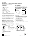
The Installation Space
The finished cutout width must be 35-1/2".
Product Dimensions
* Shipping Height. The
refrigerator can be adjusted
to fit into a cutout that is
83-1/2" min. to 84-1/2" max.
height.
The top case trim at the front
is 1/2" higher and will overlap
upper cabinetry or soffit.
Use leveling legs and wheels
for a maximum 1" height
adjustment.
The cutout depth must be 24"
The refrigerator will project forward, slightly beyond adjacent
cabinetry, depending on your installation.
The cutout depth beneath a soffit:When installed beneath
a soffit, the soffit cannot exceed the 24" installation depth
shown. The top case trim overlaps the bottom of the soffit.
Electrical: A 115V, 60Hz., 15 or 20 amp power supply is
required. An individual properly grounded branch circuit or
circuit breaker is recommended. Install a properly grounded
3-prong electrical receptacle recessed into the back wall.
Electrical must be located on rear wall as shown.
Note: GFI (ground fault interrupter) is not recommended.
Water Line: All models are equipped with an automatic
icemaker. The water line can enter the opening through the
floor or back wall. Route GE SmartConnect
™
Kit or 1/4" O.D.
copper tubing between the cold water line and the water
connection location at the front of the refrigerator. The
installation of an easily accessible shut-off valve in the water
line is required.
696Dia7
6"
Wall View
Electrical
Area
84-1/2" max
83-1/2" min
Finished
Opening
75" From
Floor to
Bottom
of Electrical
Area
10"
5"
3 1/2"
5"
3 1/2"
24" Cutout Depth
35-1/2"
Finished Width
2-5/16"
Note: Icemaker
water connection
is at the front.
Cold Water
Supply
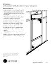
605Dia20
25"
Min. to
Wall
130°
130° Door Swing
23-7/8"
Behind
Frame
36-3/4"
605Dia21
90°
90° Door Swing
4" Min. to Wall
5" Min. for Professional Models
2-5/16"
75" From
Floor to Bottom
of Electrical
Area
84-1/2" max
83-1/2" min
Finished
Opening
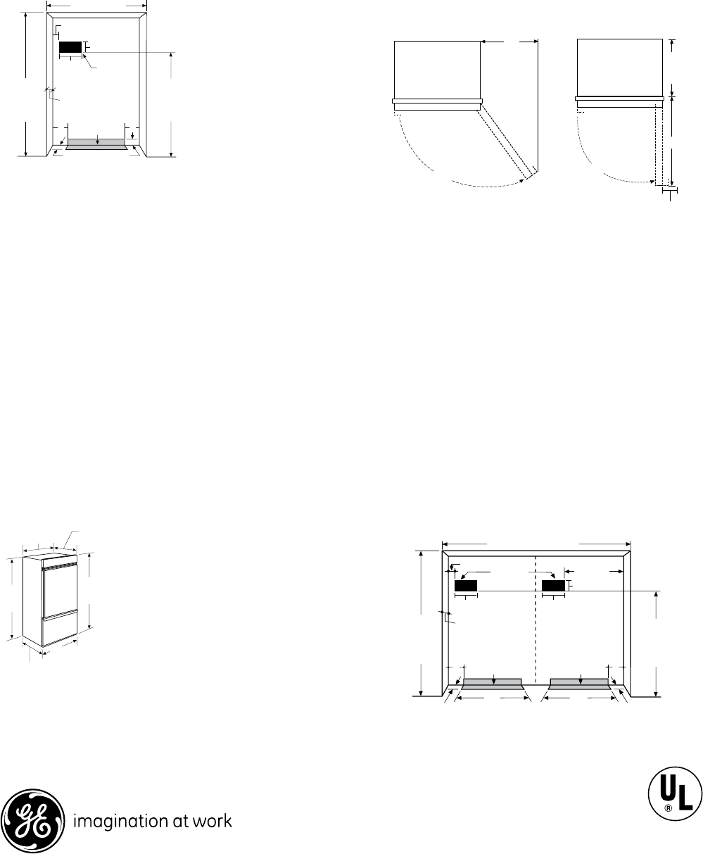
71-1/2" Finished Width
Electrical
5"
3-1/2"
24" Cutout
Depth
Water Supply
Wall View
696Dia8
24-3/16"
26"
6"
10"
10"
Water Supply
26"
5"
3-1/2"
Door Swing Clearances
The installation must allow for clearances to adjacent walls or
cabinets. These refrigerators are equipped with a 2-position
door stop. The factory-set 130° door swing can be adjusted to
90° if clearance to adjacent cabinets or walls is restricted.
Allow 25" minimum clearances for a full 130° door swing. Allow
15" for pan removal.
• 4" minimum clearance is required when the door swing is
adjusted to 90°. If the 90° door stop position is used, pan
access is maintained, but pan removal is restricted.
• See door swing illustrations to determine interaction with
adjacent cabinets or countertops.
ZUG2, ZUGSS2 Unified Grille Panel Kit
• If you are installing two refrigerators side by side, the
installation space must be 71-1/2" wide.
Note: Additional cutout width may be required when side panels
are used. Add side panel thickness to the finished cutout to
calculate rough-in width.
• The water and electrical locations for each product must be
located as shown.
• A separate 115V, 60Hz., 15 or 20 amp power supply is
recommended for each product.
429Dia9
*84" From
Floor to
Top Frame
35"
Case Width
*83-1/2"
at
Rear
Case Depth:
25-3/8" Framed Models
25-3/4" Stainless Steel Models
Depth Including Handles:
26-7/8" Framed Models
27-3/4" Stainless Steel Models
28-11/16" Professional Models
36"
Frame to Frame Width