


Features
• Milli-volt system compatible
• Low battery indicator.
• Fahrenheit/Celsius display option.
• Adjustable from 45°F (4°C) to 90°F (32°C).
• Accuracy within ±1 degree.
•Adjustable temperature differential: .5 – 1.5 degree.
• Low temperature freeze protection. While in heat mode, thermostat
will mechanically turn on heat if temperature drops to 40°F (4°C) -
even if batteries are missing or drained.
• Automatic heating shutdown if temperature exceeds 90°F (32°C).
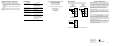
Replacing Existing Thermostat
1. Turn off power to heating and cooling system.
2. Remove cover of old thermostat to expose wires.
Do not disconnect wires. (Fig. 1)
3. Label wires per Table 1.
Table 1
Old Label New Label Description
M, 4, RH, R5 or R R Heat Transformer,
hot side
H, W or 4 W Heating control
F or G G Fan control relay
*NOTE: ON SOME OLDER MODELS, THE C TERMINAL CAN BE EITHER THE COOLING CONTROL OR THE
COMMON SIDE OF THE TRANSFORMER
. CHECK FURNACE WIRING DIAGRAM TO VERIFY C TERMINAL. IFIT
IS THE COMMON SIDE OF THE TRANSFORMER
, CAP THE WIRE AND TUCK INTO THE WALL.
4. After labeling wires, remove wires from terminals.
5. Remove existing thermostat base from wall.
6. Refer to the following section for instructions on how to
install thermostat.
Installing Model 9505 Thermostat
NOTE: FOR NEW INSTALLATIONS, MOUNT THERMOSTAT ON INSIDE WALL, 4-5 FEET ABOVE THE FLOOR.
DONOT INSTALL BEHIND A DOOR, IN A CORNER, NEAR AIR VENTS, IN DIRECT SUNLIGHT, OR NEAR ANY
HEAT OR STEAM GENERATING FIXTURES
. INSTALLATION AT THESE PLACES WILL AFFECT THERMOSTAT
OPERATION
.
1. Turn power off to the heating
and cooling systems.
2. Place SYSTEM ON-OFF
In OFF position.
3. Place AUTO-ON switch
Into AUTO position.
4. Remove the cover using a coin
or screwdriver.
5. Place thermostat against the wall at desired location. Make sure
wires will feed through opening on base of thermostat.
6. Mark placement of mounting holes. See Fig. 3.
Set base aside.
7. Drill the marked holes using a 3/16" drill bit. NOTE: Enclosed plastic
anchors do not require a drilled hole for drywall.
8. Tap plastic anchors into the wall.
9. Align base with plastic anchors and feed wires
through opening.
10. Secure base to wall with supplied screws.
11. Connect wires to terminal strip. Refer to wiring diagrams on other
side of this sheet. Make sure wire connections are secure.
12. Place fan option switch into either the "ELEC" or "GAS" position
depending upon the type of furnace. Refer to Figure 4
Figure 4
13. Put the °F/°C switch to either °F for Fahrenheit display
or °C for Celsius display readout.
14. Install two “AA” ENERGIZER brand batteries or equivalent into bat-
tery compartment. Be sure to match positive (+) ends of batteries
with positive (+) battery terminals in the battery compartment. The
display will show as follows:
15. Replace cover onto thermostat by snapping into place.
16. Turn on power to system . Test thermostat as described in the fol-
lowing section.
To Test Thermostat
WARNING: DO NOT SHORT (JUMPER) ACROSS TERMINALS OF GAS VALVE OR SYS-
TEM CONTROL TO TEST OPERATION. THIS WILL DAMAGE THE THERMOSTAT AND
VOID YOUR WARRANTY.
1. Place the SYSTEM: ON-OFF
switch into the ON position
2. Press the button until the
temperature setting is at east
3 degrees above the room
temperature. The heating
system should turn on within
a few seconds.
3. Put the SYSTEM: ON-OFF
switch into the OFF position.
The heating system
should turn off.
4. Put the AUTO-ON switch
to the ON position. The blower
fan should turn on.
5. Put the AUTO-ON switch
to the AUTO position. The
blower fan should turn off.
NOTE: Some heat only systems do not have a separate fan control.
Operation
Setting or Changing the Setpoint Temperature
1. Press either the or button.
The display will show the current
temperature setpoint.
2. Press either the or button
to adjust the temperature setting
either up or down.
The display will return to the room temperature display five seconds after
the last input and the new setpoint will be saved.
Changing Temperature Differential
IMPORTANT: The temperature differential is factory set at 1 (.5°). This
means that whenever the room temperature changes by one half of a
degree from the temperature setting, the system will turn on. If the
system turns on too often, increase the temperature differential.
1. Press both and buttons
at the same time and hold for one
second. The display will show:
2. Press either the or button
to adjust the temperature
differential up or down.
The display will return to the room temperature five
seconds after the last input.
IMPORTANT SAFETY INFORMATION
WARNING:
• Always turn off power at the main power source by unscrewing
fuse or switching circuit breaker to the off position before installing,
removing, cleaning or servicing thermostat.
• Read all of the information in this manual before installing or pro-
gramming this thermostat
•This is a 24V AC low-voltage thermostat. Do not install on voltages
higher than 30V AC.
• All wiring must conform to local and national building and electrical
codes and ordinances.
• Do not short (jumper) across terminals on the gas valve or at the
system control to test installation. This will damage the thermostat
and void the warranty
1 2 3 4 5 6
>
>
>
>
>
>
SYSTEM: ON-OFF AUTO - ON
>
>
SYSTEM: ON-OFF
AUTO - ON
SYSTEM: ON-OFF AUTO - ON
>
>
>
>
SYSTEM: ON-OFF AUTO - ON
>
>
>
>
Figure 1
Figure 2
MOUNTING HOLES
ELEC/
GAS SWITCH
°F/°C
Switch
SYSTEM: ON-OFF
SYSTEM: ON-OFF
AUTO - ON
>
AUTO - ON
>
>
1 Heat
W
A
R
R
A
N
T
Y
INTEGRATED COMFORT SOLUTIONS
™
DIGITAL
NON-PROGRAMMABLE
THERMOSTAT
9505
User’s Manual
Quick Start
Installation and
Programming
110-735
®
ELECTRIC
E
GAS
G
MILLIVOLT
M
Differential
Setting Degrees
1.5°
2 1.0°
3 1.5°
110-735B