


D400-13-00 1 I56-555-09R
DH400ACDCP Air Duct Smoke Detector
INSTALLATION AND MAINTENANCE INSTRUCTIONS
3825 Ohio Avenue, St. Charles, Illinois 60174
1-800-SENSOR2, FAX: 630-377-6495
www.systemsenor.com
Before Installing
Please thoroughly read the System Sensor Guide for
Proper Use of Smoke Detectors in Duct Applications
(A05-1004), which provides detailed information on de-
tector spacing, placement, zoning, wiring, and special
applications. Copies of this manual are available online
at www.systemsensor.com or via System Sensor’s toll free
fax-back service, Documents on Demand at 800/736-7672.
NFPA Standards 72 and 90A should also be referenced for
detailed information.
NOTICE: This manual should be left with the owner/user
of this equipment.
IMPORTANT: This detector must be tested and maintained
regularly following NFPA 72 requirements. The detector
should be cleaned at least once a year.
Table of Contents Page
[1] General Description 1
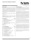
[2] Exploded View of Duct Detector Components 2
[3] Contents of the Duct Detector Kit 2
[4] Limitations of Duct Detectors 2
[5] Installation Sequence 2
[6] Duct Detector Maintenance and Test Procedures 8
[7] Detector Cleaning Procedures 10
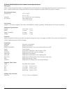
[8] Specifications 12
Warranty 13
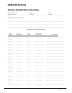
Detector Test log 16
List of Tables and Figures Page
Fig. 1: Duct Detector Exploded View 2
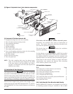
Fig. 2: Installation of Sampling Tube Gaskets 3
Fig. 3: Mounting Location of Speed Nuts 3
Table 1: Inlet Sampling Tube Selection 3
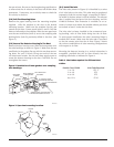
Fig. 4: Inlet Sampling Tube 4
Fig. 5: Sampling Tube Mounting Configurations 4
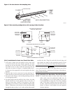
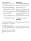
Fig. 6: Wiring Diagram 6
Fig. 7: Wiring Diagram – No Control Panel 7
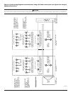
Fig. 8: Wiring Diagram – Accessories 8
Fig. 9: Sampling Tube Filter Installation 8
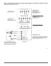
Fig. 10: Testing Detector Alarm 9
Fig. 11: Detector Head Removal 9
Fig. 12: RTS451/RTS451KEY Test Coil Installation 10
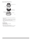
Fig. 13: Photo Head Exploded View 11
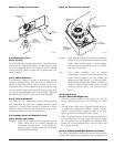
[1] General Description
An HVAC system supplies conditioned air to virtually ev-
ery area of a building. Smoke introduced into this air duct
system will be distributed to the entire building. Smoke
detectors designed for use in air duct systems are used to
sense the presence of smoke in the duct.
Model DH400ACDCP Air Duct Smoke Detector utilizes
photoelectric technology for the detection of smoke. This
smoke detection method, when combined with an efficient
housing design, samples air passing through the duct and
allows detection of a developing hazardous condition.
When sufficient smoke is sensed, an alarm signal is initi-
ated at the fire control panel monitoring the detector, and
appropriate action can be taken to shut off fans and blow-
ers, change over air handling systems, etc. These actions
can facilitate the management of toxic smoke and fire gases
throughout the areas served by the duct system.
DH400ACDCP detectors are designed to operate from 24
VDC, 24 VAC, 120 VAC, or 240 VAC. Alarm and supervisory
relay contacts are available for control panel interface
(alarm initiation), HVAC control, and other auxiliary func-
tions. These detectors are not designed for 2-wire appli-
cation.
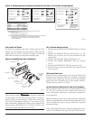
For testing, the alarm can be enabled by a magnet activated
test switch, by insertion of a calibrated test card into the
sensing chamber (photoelectronic version only), or by the
optional remote test station. The duct smoke detectors latch
into alarm state when alarm occurs. LEDs on each detector
illuminate to provide local alarm indication, and optional
accessories offer a variety of annunciation capabilities.
The detector can be reset by a momentary power inter-
ruption, by the magnet activated reset switch, or by the
optional remote test station.