EPSON Stylus Color 600 Service Manual
Rev. A
3-1
3.2.5 Disassembling the Printer Mechanism
This section describes the procedures for removing the main components consisting the printer mechanism.
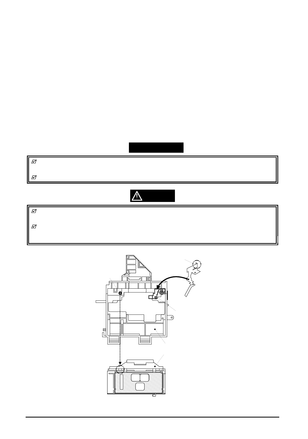
3.2.5.1 Printhead Removal
1. Removing the upper housing. (Refer to section 3.2.1)
2. Rotate “Gear, 67.2” (largest gear at the left-hand side of the printer mechanism) toward the front to
disengage the carriage lock mechanism, and move the carriage assembly to the middle of the
printer.
3. Remove both black and color ink cartridges.
4. Remove both carriage cover assemblies from the carriage.
5. Remove “Twist Spring, 49” at left-hand side of the carriage and remove 1 screw (No.3) fixing
“FASTNER, HEAD”. Then, remove “FASTNER, HEAD” from the carriage.
6. Unhook the flat cables from the carriage assembly and tae out the printhead unit from the
carriage.
7. Disconnect the cables from the connector of the printhead unit.
WORK POINT
Notice that the grounding plate is installed in correct position. (there are two fixing pins in the
carriage)
Be sure that fixing pin of the carriage is correctly located into the cut out of the printhead unit.
CAUTION
Once the ink cartridge is removed, it is not re-usable and always install brand-new ink cartridge
before returning the printer to the user.
When returning the printer to the user, be sure that the ink cartridge is installed and the carriage
is at the capping position. (Turn the printer off while the carriage is at the capping position and
pack it)
Print Head
Carriage Assembly
Make sure that protrusion
of carriage is in the hole
of the earth board.
This part should
be touching the
CR axis receiver.
Make sure that this
protrusion is in the
U ditch of the priht head
side.
Figure 3-7.Printhead Installation


