MG500-EU-EN v1.0 7/13
6
MeterPreparation
Warning:Ensurethatthecircuitundertestdoesnotincludedevicesorcomponentsthatcanbe
damagedby10KVDC;suchdevicesincludepowerfactorcorrectioncapacitors,lowvoltagemineral
insulatedcables,electroniclightdimmers,ballastsandstartersforfluorescentlamps.
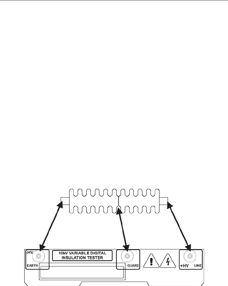
ConnectingtheTestLeadstothemeter
o ConnecttheRed(Line)testleadtotheRedtestjackonthemeter.
o Connectthebluelead(attachedtotheRedtestlead)totheBluetestjackonthemeter.
o ConnecttheGreen(Earth)testleadtotheGreentestjackonthemeter.
OptionalLeakageguard
ConnecttheoptionalBlue(Leakageguard),testleadtotheBluetestjack.
NOTE:TheBlue(Leakageguard)leadisattacheddirectlytothetopoftheBlueguardleadofthe
Redtestlead.
ConnectingtheTestLeadstothedeviceundertest
Warning:makesurethatthecircuitundertestisde‐energized.
o ConnecttheGreen(Earth)leadtotheEarthorgroundsideoftheinsulatorunderTest.
o ConnecttheRed(Line)testleadtotheothersideoftheInsulatorundertest.
o OptionalLeakageguard:Connectthe
Blue(Guard)leadtotheinsulatorsheathingand
coveringmaterialasshownonthediagram.Useacopperwirewrappedaroundthe
insulatorataboutitscenter.


