28
maintenance
configuration
single-UPS unit
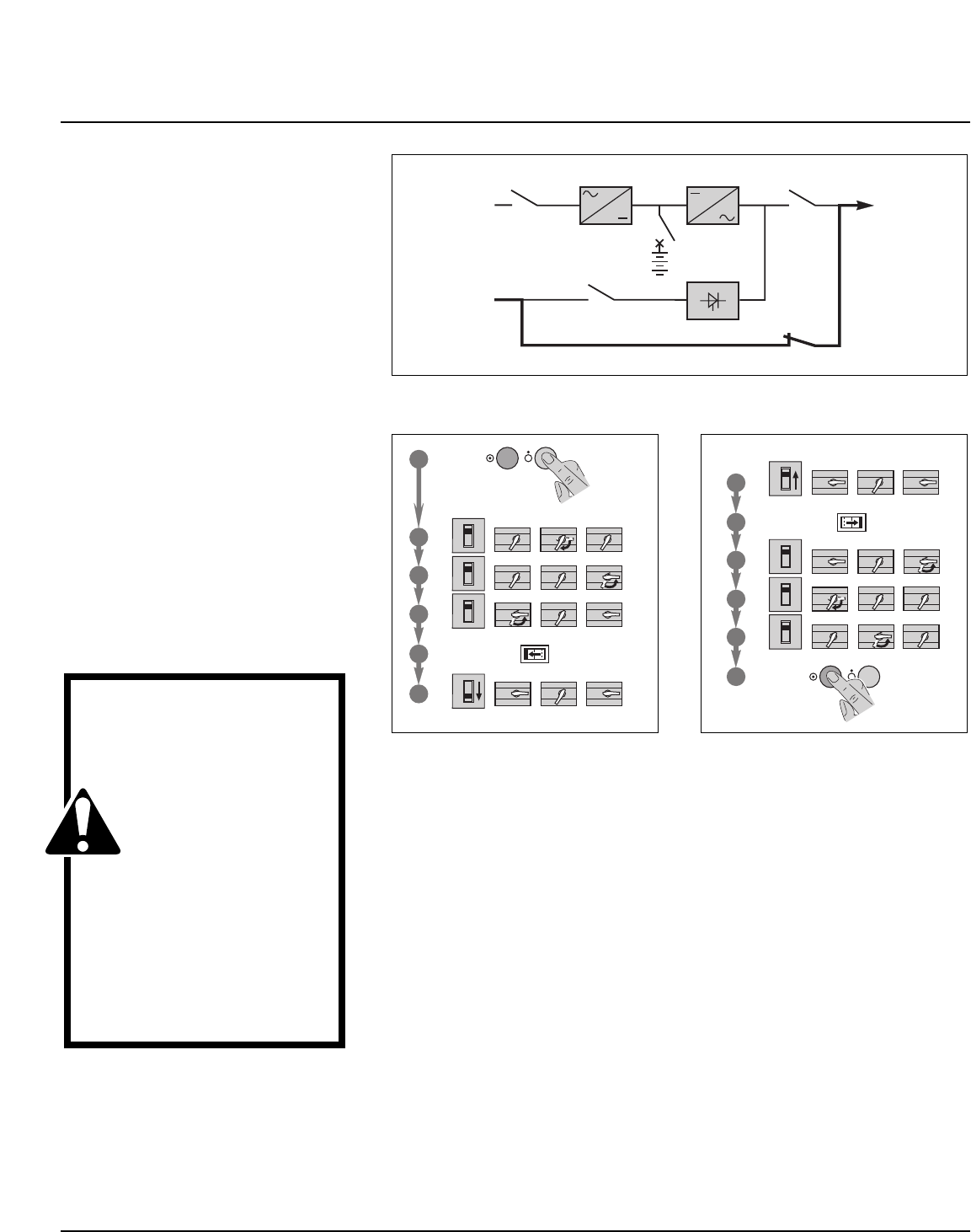
See figure 19. During maintenance, the
UPS must be isolated from the normal and
bypass AC source, the battery and the
load.
■ UPS isolation
Proceed in the following order (see figure
20):
❏ shut down the inverter (press the "invert-
er OFF" button 8 for three seconds),
❏ close bypass switch Q3BP,
❏ open isolating switches Q5N, Q4S, QF1
and Q1.
The UPS is powered down once the
capacitors have discharged (a few min-
utes);
■ start-up
Following servicing, proceed in the follow-
ing order (see figure 21):
❏ close switch Q1, then after approximate-
ly ten seconds, switches QF1, Q5N and
Q4S,
❏ open bypass switch Q3BP,
❏ start the inverter (press the "inverter ON"
button 7 ).
CAUTION
■ work should be car-
ried out in accordance
with applicable safety
regulations;
■ to avoid interrupting
the load, the various
switching operations
must be carried out in the
correct order. Operations
are explained in dia-
grams placed next to the
switches;
■ the system cabinet is
only partially powered
down. The load is still
supplied via the bypass
AC source and switch
Q3BP.
Maintenance
Fig. 21Fig. 20
Fig. 19