ANALOG INPUT SECTION 10
Page 10-6 RPC-320
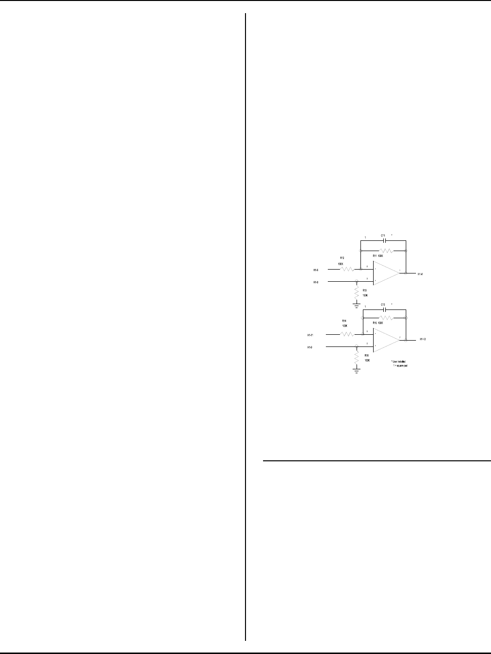
Figure 10-2 Amplifier circuit
CONVERTING ANALOG
MEASUREMENTS
Inputs are converted to "real numbers" by performing
scaling calculations in the program. The AIN function
returns values from 0 to 4095. To change these numbers
into something more meaningful, use the following
formula:
var = K * AIN(n)
n is the analog channel to read. K is the scaling
constant. K is obtained by dividing the highest number
in the range of units by the maximum AIN count (4095).
Example 1: To measure the results of an A/D
conversion in volts and the voltage range is 0 to 5V,
divided 5 by 4095 to obtain K.
K = 5/4095
K = .001221
Your program could look something like:
1000 C = .001221 * AIN(N)
Example 2: You want to measure a 0 to 200 PSI
pressure transducer with a 0 to + 5V output. Divide 200
by 4095 to obtain the constant K.
K = 200 / 4095
K = .0488
The code can then look like:
1000 B = .0488 * AIN(0)
Measuring 4-20 mA current loops
Current loops is a convenient way to transmit a value
and still assure the integrity of the signal. If the line
should break, a 0 volt (or nearly so) is returned.
A 4-20 ma current loop is converted to 1 - 5V by placing
a 250 ohm resistor across the input of the channel to
ground.
Current loop r eadings are converted to engineer ing units
by performing scaling as described earlier. Since the
measur ement range is 1 to 5V, the count range is
reduced by 20% to 3276.
If pressure were measured:
K = 200/3276
K = .06105
There is one addition factor. Since the lowest value read
is 1 V, this offset is subtracted from all readings. A 1 V
offset is 1/5 of 4095 counts, or 819. The program line
then becomes:
200 A=.06105*(AIN(N)-819)
Note that if the current loop line breaks, a negative value
is returned.
AMPLIFIERS
Two operational amplifiers are available to signal
condition inputs. Each amplifier is configured as shown
below.
Amplifiers are accessed through header connector H1.
Pin out is as follows:
H1 pin Function
1 Temperature output from U14
2 To channel 0 analog input
3 Non-inverting input, amplifier A
4 Output from amplifier A
5 Inverting input, amplifier A
6 Approximately + 7V supply (5 ma
maximum)
7 Ground
8 Ground
9 Non-inverting input, amplifier B
10 Approximately -7V supply (5 ma
maximum)
11 Inverting input, amplifier A
12 Output from amplifier A


