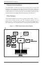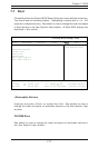
5-14
SUPERSERVER 6012P-6 User’s Manual
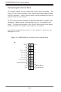
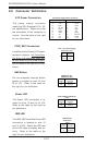
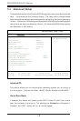
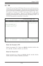
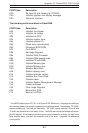
Extra Universal Serial Bus
Headers (FPUSB0/1)
The Front Panel USB0/USB1 head-
ers are located at JD2. These are
separate from the ports on the I/O
panel. You will need a USB cable
(not included) to use either con-
nection. Refer to the table on the
right for pin definitions.
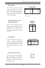
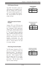
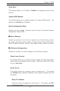
Power Button
The Power Button connection is
located on pins 1 and 2 of JF2.
Momentarily contacting both pins
will power on/off the system. This
button can also be configured to
function as a suspend button (see
the Power Button Mode setting in
BIOS). To turn off the power
when set to suspend mode, de-
press the button for at least 4
seconds. Refer to the table on the
right for pin definitions.
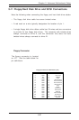
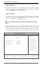
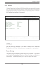
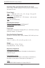
Pin
Number
1
2
Definition
PW_ON
Ground
Power Button
Connector
Pin Definitions
(JF2)
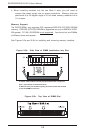
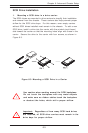
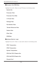
Universal Serial Bus
(USB0/1)
Two Universal Serial Bus ports
are located beside the PS/2 key-
board/mouse ports. USB0 is the
bottom connector and USB1 is the
top connector. See the table on
the right for pin definitions.
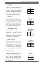
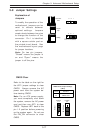
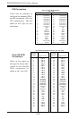
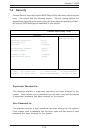
Universal Serial Bus Pin Definitions
Pin
Number Definition
1+5V
2P0-
3P0+
4 Ground
5 N/A
Pin
Number Definition
1+5V
2P0-
3P0+
4 Ground
5Key
USB0
USB1
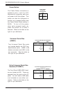
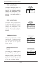
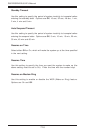
Front Panel Universal Serial Bus Pin
Definitions
Pin
Number Definition
1+5V
2P0-
3P0+
4 Ground
5 N/A
Pin
Number Definition
1+5V
2P0-
3P0+
4 Ground
5Key
FPUSB0
FPUSB1