Chapter 5: Advanced Serverboard Setup
5-13
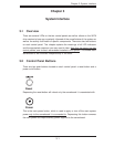
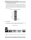
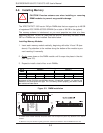
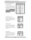
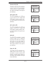
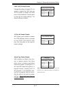
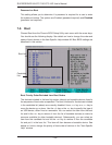
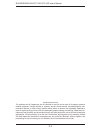
Overheat LED (OH)
Connect an LED to the OH connection
on pins 7 and 8 of JF1 to provide ad-
vanced warning of chassis overheat-
ing. Refer to the table on the right for
pin defi nitions.
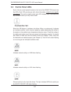
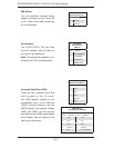
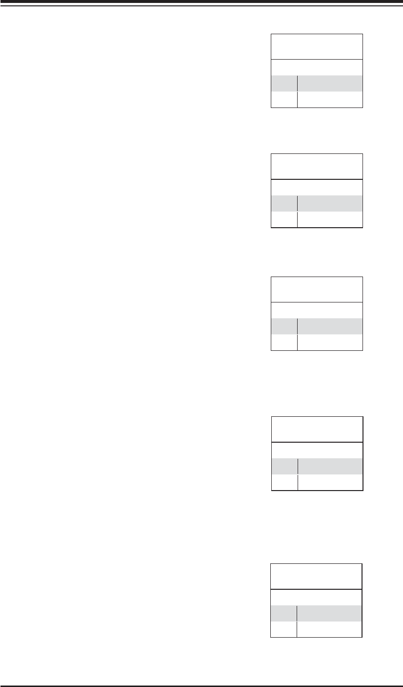
NIC2 (LAN2) LED
The LED connections for LAN2 are
on pins 9 and 10 of JF1. Attach LAN
LED cables to display network activ-
ity. See the table on the right for pin
defi nitions.
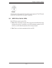
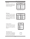
HDD LED
The HDD LED connection is located
on pins 13 and 14 of JF1. Attach the
hard drive LED cable here to display
disk activity (for any hard drives on
the system, including Serial ATA and
IDE). See the table on the right for
pin defi nitions
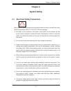
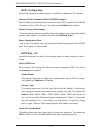
OH/Fan Fail LED
Pin Defi nitions (JF1)
Pin# Defi nition
7 Vcc
8 Ground
NIC1 LED
Pin Defi nitions (JF1)
Pin# Defi nition
11 Vcc
12 Ground
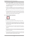
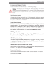
NIC2 LED
Pin Defi nitions (JF1)
Pin# Defi nition
9 Vcc
10 Ground
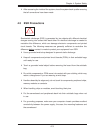
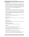
HDD LED
Pin Defi nitions (JF1)
Pin# Defi nition
13 Vcc
14 HD Active
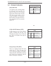
NIC1 (LAN1) LED
The LED connections for LAN1 are
on pins 11 and 12 of JF1. Attach LAN
LED cables to display network activ-
ity. See the table on the right for pin
defi nitions.
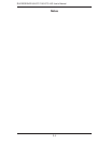
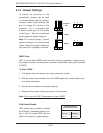
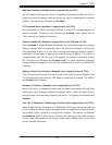
Power On LED
The Power On LED connector is lo-
cated on pins 15 and 16 of JF1. This
connection is used to provide LED
indication of power being supplied to
the system. See the table on the right
for pin defi nitions.
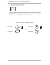
Power LED
Pin Defi nitions (JF1)
Pin# Defi nition
15 5V Stby
16 Control