Chapter 2: Installation
2-21
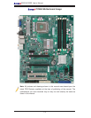
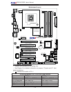
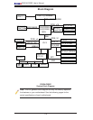
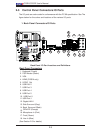
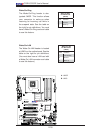
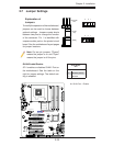
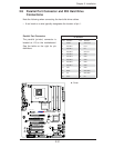
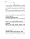
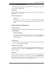
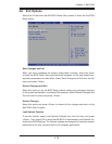
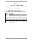
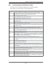
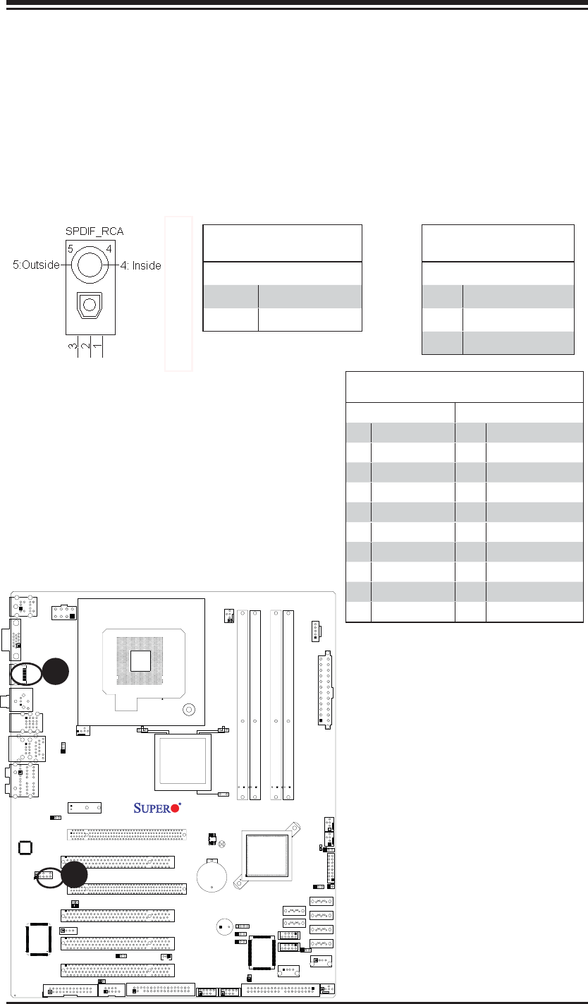
JL1
JI2C1
JI2C2
JOH1
JPUSB1
JPI1
JWD1
JPL1
JPAC
JLED1
JPD1
COM1
JPW1
Floopy
JPW2
JWOL1
SMBUS_PS1
DIMM1
DIMM2
CD1
JBT1
SPKR1
LE1
JD1
Fan5
Fan4
Fan1
Fan3
Fan2
LAN1
JPUSB2
DIMM2B
DIMM4
DIMM3
USB 10/11
USB 8/9
USB6
1394_2
Slot7 PCI-E x1
Slot6 PCI-E Gen2 x16
Slot3 PCI 33MHz
HD AUDIO
JWOR
CPU
CPU Fan
FP Audio
1394_1
CMOS CLEAR
C2SEA/C2SEE
IDE
VGA
HDMI
USB/0/1
I-SATA3
I-SATA2
I-SATA1
I-SATA0
Slot1 PCI 33MHz
Slot5 PCI 33MHZ
Slot4 PCI-E x4 on x16
KB/MOUSE
SPI BIOS
Slot2 PCI 33MHz
DIMM2A
DIMM1B
DIMM1A
USB7
JF1
USB2/3/4/5
SPDIF_Out
Printer
I-SATA4
I-SATA5
Battery
Intel
G45 (C2SEA)
G43 (C2SEE)
ICH10
Intel
Lan
CTRL
S I/O
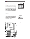
IDE
CTRL
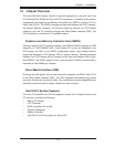
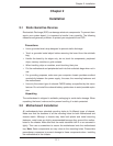
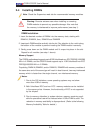
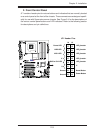
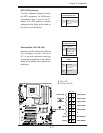
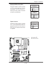
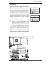
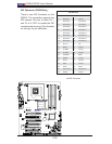
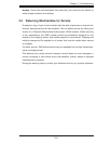
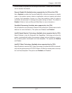
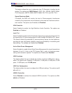
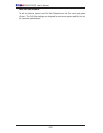
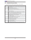
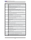
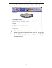
A. S/PDIF
B. HDMI Connector
A
B
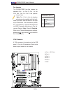
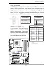
HDMI Connector (C2SEA only)
A High-Definition Multimedia Interface
(HDMI) connector is located on the IO Back-
plane on the motherboard. This connector
provides HD audio/video interface support
to the onboard audio and video connections.
See the table below for pin defi nitions.
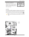
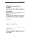
HDMI
Pin Defi nitions
Pin# Defi n. Pin# Defi n.
1 TMDS Data2+ 2 GND
3 TMDS Data2- 4 TMDS Data1+
5 GND 6 TMDS Data1-
7 TMDS Data0+ 8 GND
9 TMDS Data0- 10 TMDS Clock+
11 GND 12 TMDS Clock-
13 CEC 14 Reversed (NC)
15 SCL 16 SDA
17 DDC/CED GND 18 +5V PWR <=50mA
19 Hot Plug Detect NA
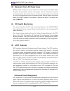
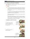
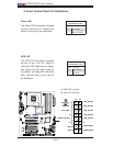
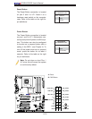
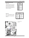
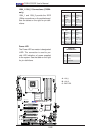
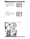
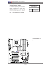
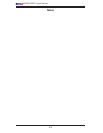
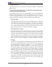
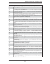
S/PDIF_Out Connector
An S/PDIF_Out connector is located next to the Backpanel USB ports on the moth-
erboard. The S/PDIF(Sony/Philips Digital Interface Format) connector is used for
transporting stereo digital audio signals. It is commonly used to connect the output of
a DVD player to a home theater receiver that supports Dolby Digital or DTS surround
sound. The S/PDIF_Out connector includes the top component (S/PDIF_RCA) and
the bottom component (S/PDIF). See the tables below for pin defi nitions.
S/PDIF (Bottom Compo-
nent) Pin Defi nition
Pin# Defi nition
1 Ground
2 Vcc
3 S/PDIF Signal
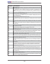
S/PDIF_RCA (Top Compo-
nent) Pin Defi nition
Pin Location Defi nition
Outside Ground
Inside S/PDIF Signal