2-10
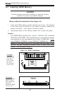
P8SC8/P8SCi User's Manual
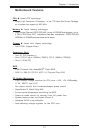
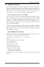
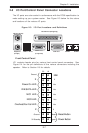
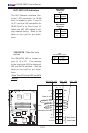
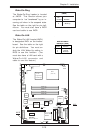
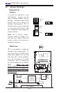
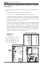
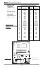
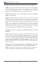
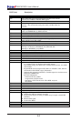
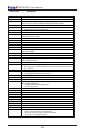
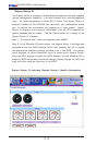
*IDE/SATA (*See the note
below)
The IDE/SATA LED is located on
pins 13, 14 of JF1. This connects
to the hard drive LED to display all
IDE and SATA activities. See the
table on the right for pin defini-
tions.
(*Note: This LED is for all IDE and SATA
devices)
Pin
Number
13
14
Definition
+5V
HD Active
IDE
Pin Definitions (JF1)
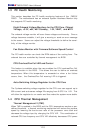
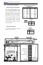
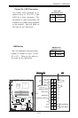
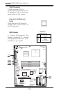
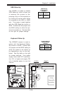
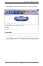
NIC1/NIC2 LED Indicators
The NIC (Network Interface Con-
troller) LED connection for GLAN
port1 is located on pins 11 and 12
of JF1 and the LED connection for
GLAN Port2 is on Pins 9 and 10.
Attach the NIC LED cables to dis-
play network activity. Refer to the
table on the right for pin defini-
tions.
NIC1 LED Pin
Definitions
(JF1)
Pin
Number
11
12
Definition
Vcc
GND
NIC2 LED Pin
Definitions
(JF1)
Pin
Number
9
10
Definition
Vcc
GND
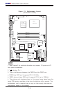
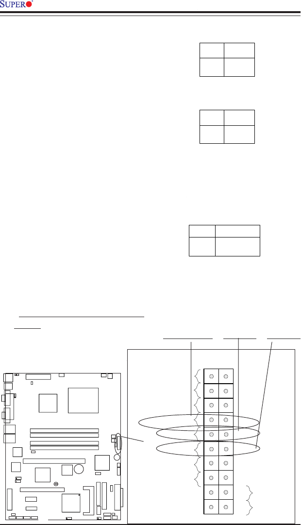
NIC1 LED
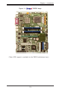
Power Butto
verheat/Fan Fail LED
1
Reset Butto
2
IDE/SATA LED
Power On LED
Reset
Signal
Vcc
Vcc
Vcc
Vcc
Ground
3V Standby
1920
Vcc
X
Ground
NMI
X
X
X
NIC2 LED
KB/MS
USB0/1
COM1
VGA
Parallel Port
JPUSB1
ATX-24 Pin PWR
JPF
JPWAKE1
4-Pin
PWR
CPU
CopperRiver
NorthBridge
GLAN1
GLAN2
DIMM 1A
DIMM 1B
DIMM 2A
DIMM 2B
GLAN
CTRL
GLAN
CTRL
JPL1
JPL2
PCI-X 133/100 MHz
PCI-Ex1
(L
G
A
7
7
5
)
SCSI CTRL
7902 W
S
C
S
I C
h
a
n
n
e
l A
SCSI Channel B
J
W
D
U
S
B
6
/7
B
IO
S
J
L
1
ID
E
F
lo
p
p
y
J
5
J
B
T
1
J
F
1
J
L
E
D
F
a
n
3
F
a
n
2
J
S
L
E
D
Fan1
Fan5
Fan4
IC
H
6
R
S
o
u
th
B
rid
g
e
PXH-V
PCI 33MHz
B
a
tte
ry
PCI-Ex1
S
A
T
A
3
S
A
T
A
2
S
A
T
A
1
S
A
T
A
0
J
W
O
R
J
P
A
1
IP
M
I
C
O
M
2
U
S
B
2
/3
B
u
z
z
e
r
W
O
L
JBT1
J
9
J
S
L
E
D
LE1
E7221
NIC2 LED NIC1 LEDIDE/SATA LED