C-6
SC827 Chassis Manual
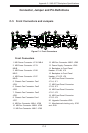
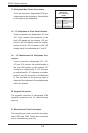
21. Manufacturer's Test Connectors
The manufacturer's test connectors are desig-
nated JP26 and JP49. These test connectors
are for manufacturing use only.
20. Upgrade Connector
The upgrade connector is designated JP69
Upgrade connectors are for manufacturing
use only.
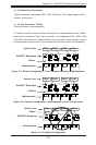
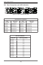
16. - 19. Motherboard to Backplane Con-
nectors
These connectors, designated JF1, JF2,
JF3 and JF4 connect the motherboards to
the front LED panels on the chassis. JF1
connects to motherboard A. JF2 connects
to motherboard B. JF3 connects to mother-
board C and JF4 connects to motherboard
D. See the table on the previous page to
determine the locations of the motherboards
within the chassis.
14. - 15. Backplane to Front Panel Headers
These connectors are designated JF5 and
JF6. They connect the backplane to the
front LED panels on the chassis. JF5 con-
nects to the LED display panel for mother-
boards A and B. JF6 connects to the LED
display panel for motherboards C and D.
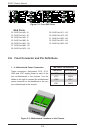
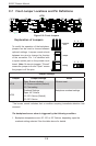
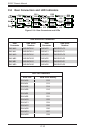
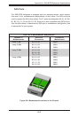
Backplane
Main Power
4-Pin Connector
(JP48)
Pin# Denition
1 +12V
2 and 3 Ground
4 +5V_STBY
13. Backplane Main Power Connectors
The 4-pin connector, designated JP48 pro-
vides power to the backplane. See the table
on the right for pin denitions.