Chapter 5: Advanced Motherboard Setup
5-19
NC = No Connection
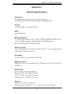
Power Supply I
2
C Connector
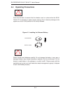
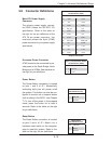
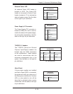
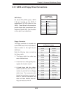
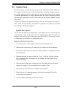
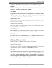
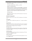
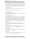
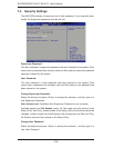
The Power Supply (I
2
C) connector is
located at SMB_PS1 and is used to
monitor the status of the power supply,
fan and system temperature. See the
table on the right for pin defi nitions.
PWR Supply I
2
C
Pin Defi nitions
Pin# Defi nition
1 Clock
2 Data
3 PWR Fail
4 Ground
5 3.3V
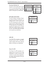
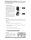
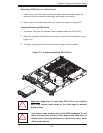
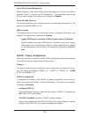
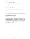
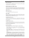
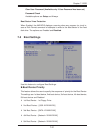
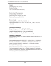
Onboard Power LED
An onboard Power LED header is
located at JLED. This Power LED
header is connected to Control Panel
header located at JF1 to indicate the
status of system power. See the table
on the right for pin defi nitions.
Onboard PWR LED
Pin Defi nitions
Pin# Defi nition
1 VCC
2 No Connection
3 Connection to PWR
LED in JF1
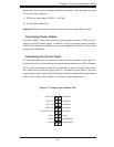
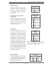
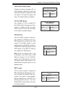
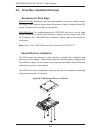
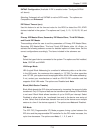
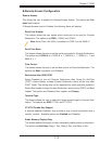
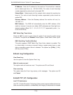
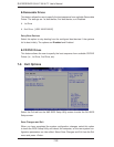
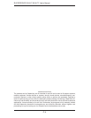
Serial_Link-SGPIO
Pin Defi nitions
Pin# Defi nition Pin Defi nition
1NC 2 NC
3 Ground 4 DATA Out
5 Load 6 Ground
7 Clock 8 NC
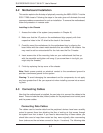
T-SGPIO 0/1 Headers
Two T-SGPIO (Serial-Link General
Purpose Input/Output) headers are
located near the SATA connectors
on the motherboard. These headers
are used to communicate with the
enclosure management chip in the
system. See the table on the right for
pin defi nitions.
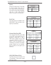
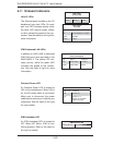
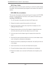
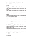
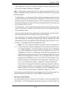
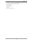
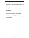
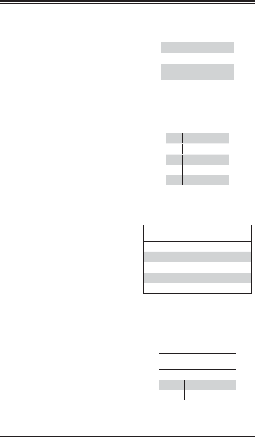
Alarm Reset
If three power supplies are installed
and Alarm Reset (JAR) is connected,
the system will notify you when any of
the three power modules fail. Connect
JAR to a micro-switch to turn off the
alarm that is activated when a power
module fails. See the table on the right
for pin defi nitions.
Alarm Reset
Pin Defi nitions
Pin Setting Defi nition
Pin 1 Ground
Pin 2 +5V