Chapter 2: Installation
2-7
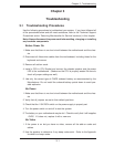
®
S
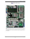
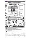
UPER X7DVL-3
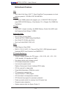
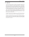
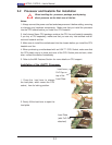
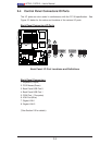
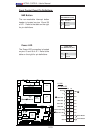
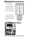
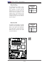
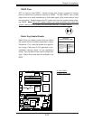
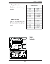
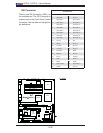
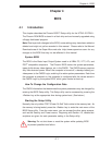
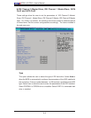
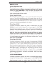
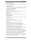
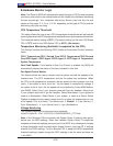
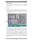
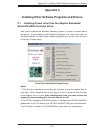
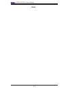
To Install: Insert module vertically and press down until it
snaps into place. Pay attention to the alignment notch at
the bottom.
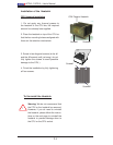
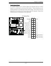
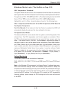
Installing and Removing DIMMs
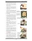
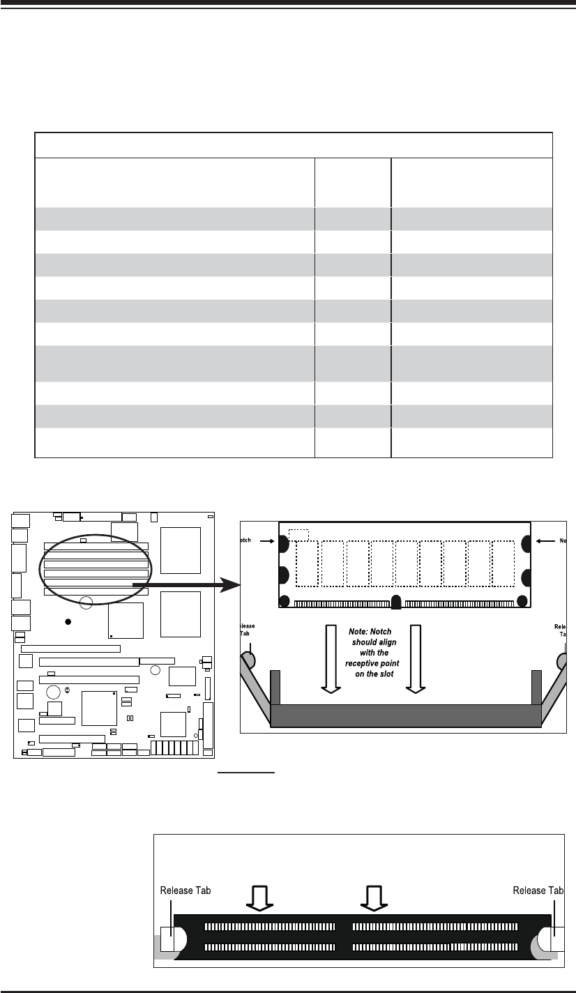
To Remove:
Use your thumbs
to gently push the
release tabs near
both ends of the
module to release
it from the slot.
DDR2 FBD DIMM
Top View of DDR2 FBD Slot
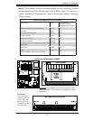
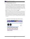
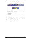
Note 2: Due to memory allocation to system devices, memory remaining available
for operational use will be reduced when 4 GB of RAM is used. The reduction in
memory availability is disproportional. (Refer to the following Memory Availability
Table for details.
Possible System Memory Allocation & Availability
System Device Size Physical Memory
Remaining (-Available)
(4 GB Total System Memory)
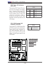
Firmware Hub fl ash memory (System BIOS) 1 MB 3.99
Local APIC 4 KB 3.99
Area Reserved for the chipset 2 MB 3.99
I/O APIC (4 Kbytes) 4 KB 3.99
PCI Enumeration Area 1 256 MB 3.76
PCI Express (256 MB) 256 MB 3.51
PCI Enumeration Area 2 (if needed) -Aligned on 256-
MB boundary-
512 MB 3.01
VGA Memory 16 MB 2.85
TSEG 1 MB 2.84
Memory available to OS and other applications 2.84