Chapter 2: Installation
2-7
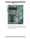
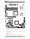
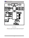
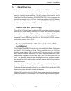
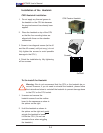
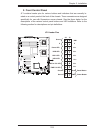
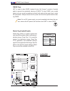
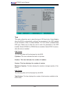
X7DWE
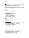
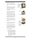
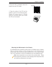
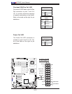
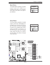
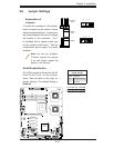
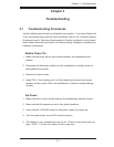
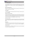
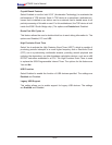
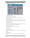
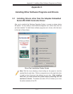
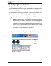
To Install: Insert module vertically and press
down until it snaps into place. Pay attention to the
alignment notch at the bottom.
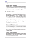
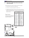
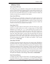
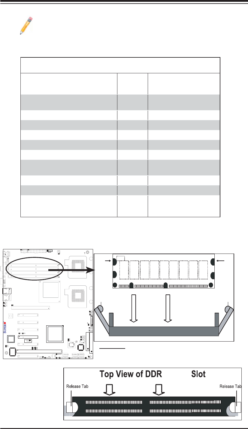
Installing and Removing DIMMs
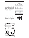
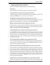
To Remove:
Use your thumbs
to gently push
the release tabs
near both ends of
the module. This
should release it
from the slot.
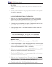
2 FBD
Note: Notch
should align
with the
receptive point
on the slot
Notch
Notch
Release
Tab
Release
Tab
DIMM2 FBD
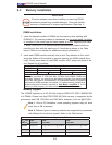
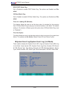
Note 3: Due to memory allocation to system devices, memory remaining
available for operational use will be reduced when 4 GB of RAM is used.
The reduction in memory availability is disproportional. (See the Memory
Availability Table below.)
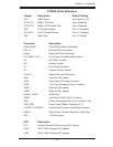
Possible System Memory Allocation & Availability
System Device Size Physical Memory
Remaining (-Available)
(4 GB Total System Memory)
Firmware Hub fl ash memory (System
BIOS)
1 MB 3.99 GB
Local APIC 4 KB 3.99 GB
Area Reserved for the chipset 2 MB 3.99 GB
I/O APIC (4 Kbytes) 4 KB 3.99 GB
PCI Enumeration Area 1 256 MB 3.76 GB
PCI Express (256 MB) 256 MB 3.51 GB
PCI Enumeration Area 2 (if needed)
-Aligned on 256-MB boundary-
512 MB 3.01 GB
VGA Memory 16 MB 2.85 GB
TSEG 1 MB 2.84 GB
Memory available for the OS & other
applications
2.84 GB