Chapter 2: Installation
2-7
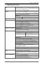
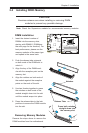
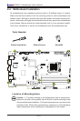
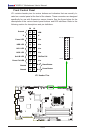
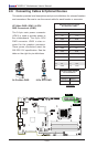
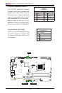
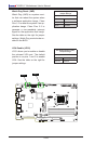
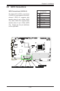
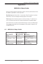
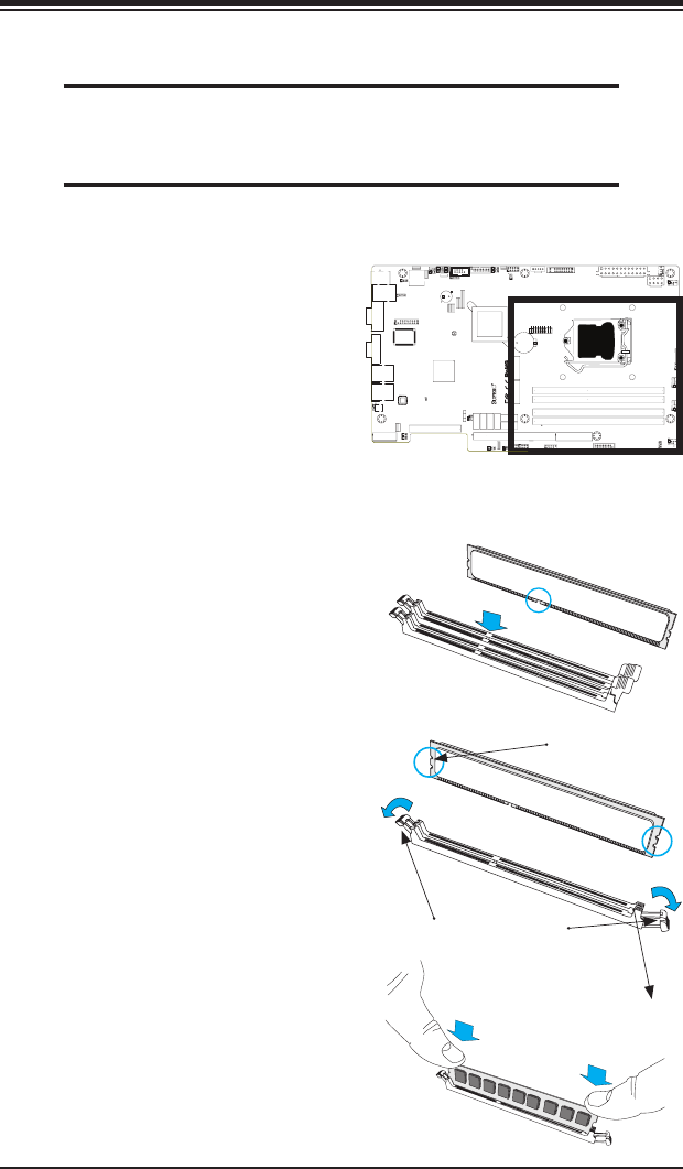
2-3 Installing DDR3 Memory
CAUTION
Exercise extreme care when installing or removing DIMM
modules to prevent any possible damage.
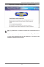
Note: Check the Supermicro website for recommended memory modules.
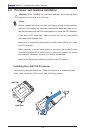
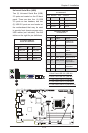
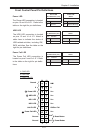
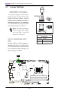
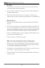
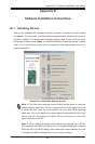
DIMM Installation
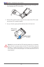
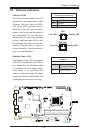
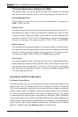
1. Insert the desired number of
DIMMs into the memory slots,
starting with DIMMA1, DIMM(see
the next page for the location). For
best performance, please use the
memory modules of the same type
and speed in the same bank.
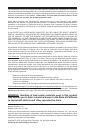
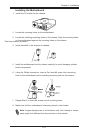
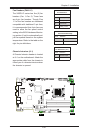
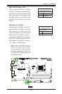
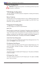
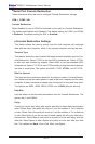
2. Push the release tabs outwards
on both ends of the DIMM slot to
unlock it.
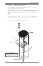
Release Tabs
Notches
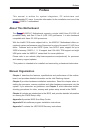
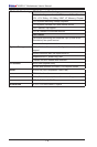
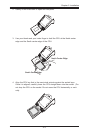
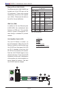
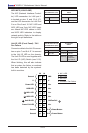
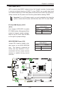
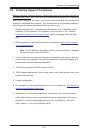
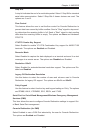
3. Align the key of the DIMM mod-
ule with the receptive point on the
memory slot.
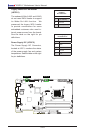
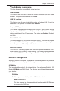
Press both notches
straight down into
the memory slot.
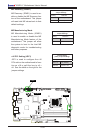
4. Align the notches on both ends of
the module against the receptive
points on the ends of the slot.
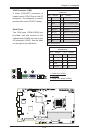
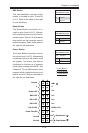
5. Use two thumbs together to press
the notches on both ends of the
module straight down into the slot
until the module snaps into place.
6. Press the release tabs to the lock
positions to secure the DIMM module
into the slot.
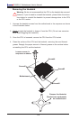
Removing Memory Modules
Reverse the steps above to remove the
DIMM modules from the motherboard.
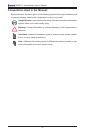
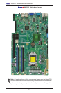
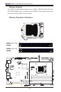
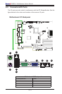
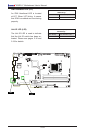
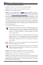
MAC CODE
BAR CODE
JSD1
1
3
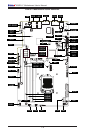
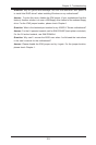
JF1
20
LE5
A
C
C768
J28
JPW2
R137
RT1
COM1
JI2C1
1
JI2C2
1
J29
1
JPME1
JPME2
JL1
7
JLAN2
JLAN1
T-SGPIO1
T-SGPIO2
+
SPKR1
J31
J15
CA
LE7
LE2
A
C
LE3
A
C
LE4
A
C
J16
JTPM
B1
+
JBT1
1
4
J5
JSPK
JPI2C
JPW1
1
SW1
1
JSTBY1
1
3
JUSB4
JUSB3
1
10
11
J1
MH8
MH4
MH3
MH7
MH2
MH5 MH6
JRF1
13
1
JPL1
1
JPL2
JLED
JWD
JPUSB1
JPB
JPG1
1
3
J8
J4
4
FAN5
FAN3
FAN1
FAN2
FAN4
J3
J2
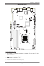
CPU
JRF1
2-3:FORCE TO X8+X8
1-2:AUTO
Buzzer/Speaker
JWD
2-3:NMI
1-2:RST
USB 3.0-0/1
SBX3: PCI-E 2.0 X4
NMI
X
ON:ME RECOVERY
JPME1
OFF:NORMAL
JPME2
OFF:NORMAL
ON:ME MANUFACTURING MODE
USB3.0-2/3
REV:1.00
X9SPU-F
JPUSB1
2-3:DISABLE
1-2:ENABLE
JPUSB1:B/P USB WAKE UP
JSPK:
JPI2C:PWR I2C
JLED:Power LED
OH/FF
COM2
JI2C1/JI2C2
OFF:Disable
ON:Enable
2-3:DISABLE
1-2:ENABLE
JPB:BMC
GNDGND5V
SBX1: PCI-E 3.0/2.0 X16 or X8+X8
DDR3 1600/1333/1066 UDIMM/RDIMM required
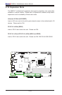
I-SATA0
I-SATA1
JSD1:DOM_PWR
SBX2: PCI-E 2.0 X4 in X8
UIOP
UID-LED
USB4/5/IPMI_LAN
I-SATA2
I-SATA3
I-SATA4
JF1
DIMMA2
DIMMA1
DIMMB1
DIMMB2
DESIGNED IN USA
2-3:DISABLE
1-2:ENABLE
JPL2 LAN2
LED
PF
KB/MS
RST
PWR ON
1
NIC
UID
2
PS
FAIL LED
PWR
HDD
1
NIC
COM1
SPEAKER
LAN1
VGA
LAN2
2-3:DISABLE
1-2:ENABLE
JPG1 VGA
CMOS CLEAR
1-2:ENABLE
2-3:DISABLE
JPL1 LAN1
USB 12/13
I-SATA5
JL1:CHASSIS INSTRUSION