2-24
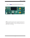
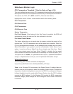
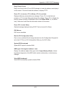
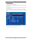
X7DBT/X7DBT-INF/X7DGT/X7DGT-INF User's Manual
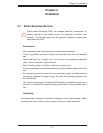
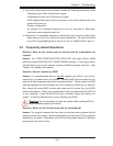
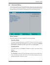
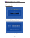
S
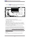
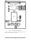
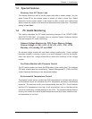
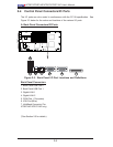
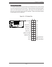
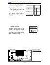
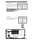
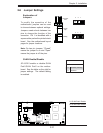
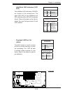
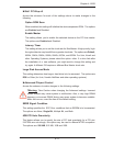
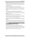
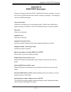
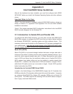
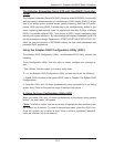
UPER X7DBT
LAN1
®
LAN2
Fan1/2
FP CTRL
SMB
Battery
N
ort
h
Bridge
VGA
Infini-
USB0/1
JPG1
South
Bridge
DIMM 1A (Bank
1)
JPL2
PCI-E x8
D
I
MM 1B
(Bank 1)
DIMM 2A
(Bank
2)
D
I
MM 2B
(Bank 2)
DIMM
3
A
(Bank
3)
DIMM 3B (Bank
3)
D
I
MM
4A (Bank 4)
DIMM 4B (Bank
4)
JBT1
JWOR
JWOL
LAN
CTRL
SIMS0
L
E3
COM2
J
PL1
SATA3
J
I
2
C1
JI
2
C2
J7
JP1
JOH1
JL1
4-
P
in
P
WR
BIOS
Buzz
er
USB2/3
CPU1
Fan3
/4
Fan5
/6
L
E
1
VGA
CTRL
S I/O
L
E2
Band
I
NF
Ctrl
Video
Memory
J
1
SATA2
SATA0
SATA1
CPU2
Fan7
/8
20-Pi
n PWR
20-P
inP
W
R
S
GPI
O
WD
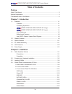
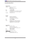
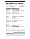
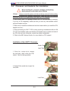
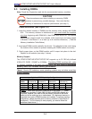
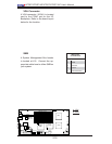
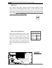
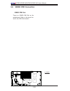
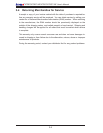
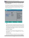
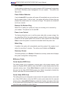
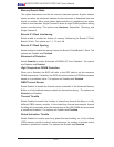
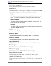
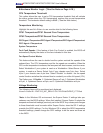
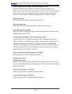
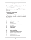
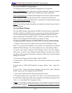
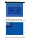
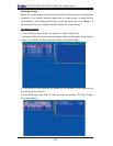
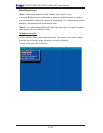
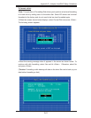
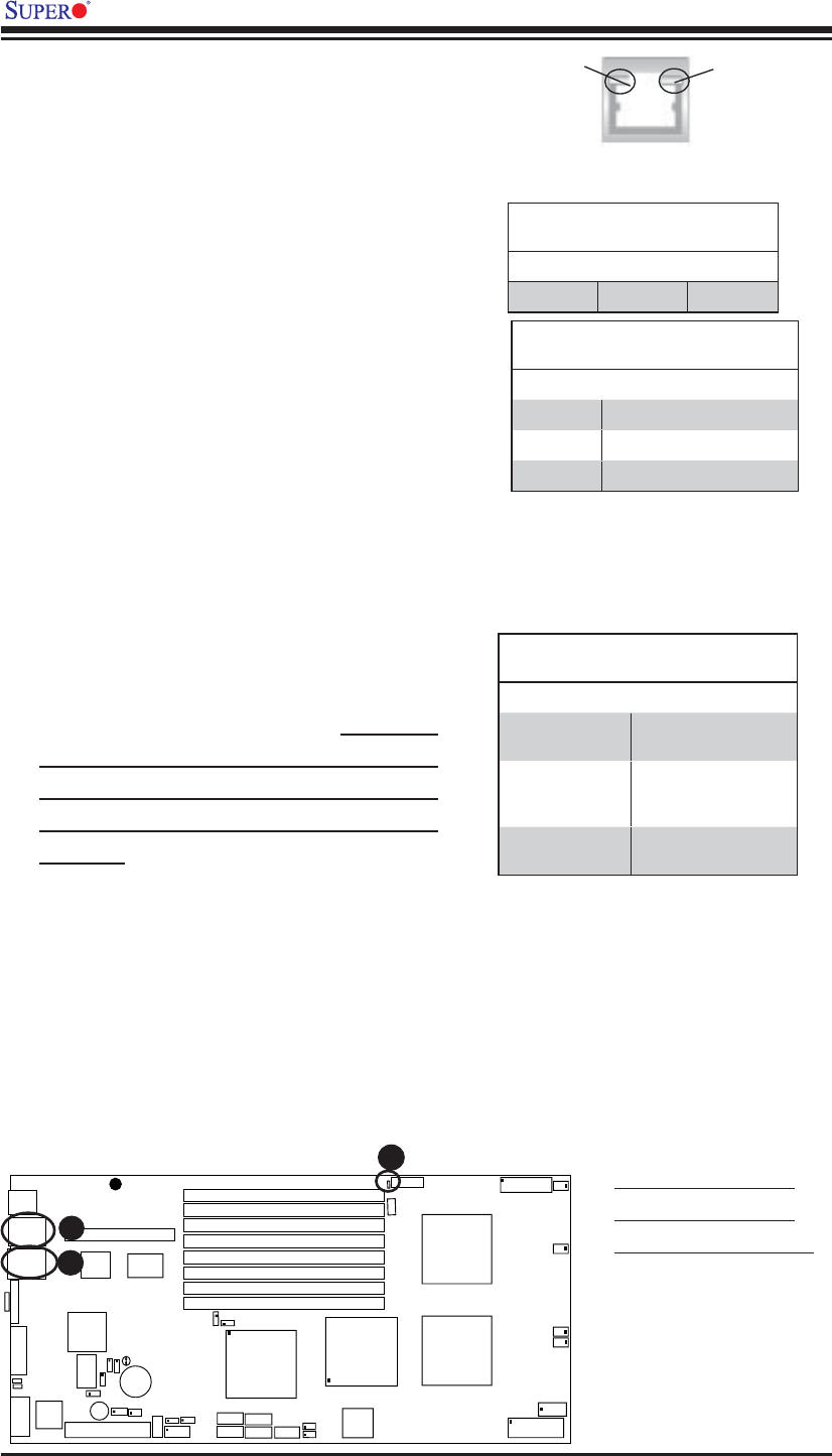
2-7 Onboard Indicators
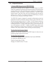
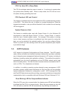
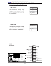
A
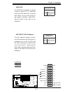
B
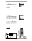
A. GLAN Port1 LEDs
B. GLAN Port2 LEDs
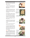
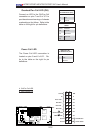
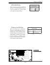
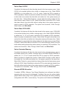
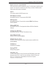
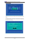
C. Onboard PWR LED
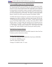
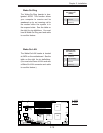
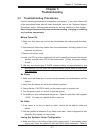
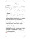
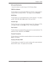
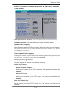
Activity
LED
Speed
LED
C
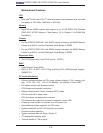
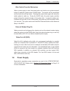
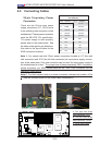
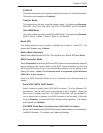
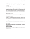
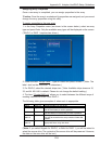
GLAN Speed LED Indicator
LED Color Defi nition
Off No Connection or 10 Mbps
Green 100 Mbps
Amber 1 Gbps
GLAN Activity Indicator
Color Status Defi nition
Yellow Flashing Active
GLAN LEDs
There are two GLAN ports on the moth-
erboard. Each Gigabit Ethernet LAN port
has two LEDs. The yellow LED indicates
activity, while the Speed LED may be
green, amber or off to indicate the speed
of the connection. See the tables at right
for more information.
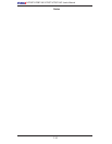
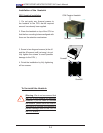
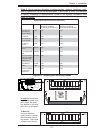
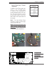
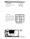
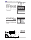
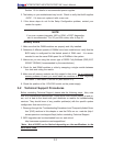
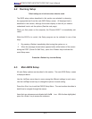
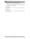
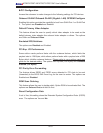
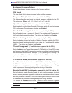
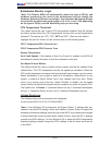
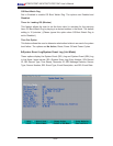
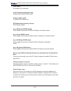
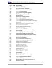
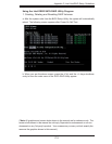
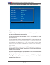
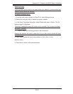
Onboard PWR LED Indicator (LE1)
LED Color Defi nition
Green (Solid) Power On, System
On
Green (Flashing) Power Standby:
power cable con-
nected, System: Off
Off Power: Off, power
cable: not connected
Onboard Power LED (LE1)
There is an Onboard Power LED (LE1)
located on the motherboard. When the
green light is on or fl ashing, the power
is connected. Unplug the power cable
before removing and changing any com-
ponents. See the layout below for the
LED location.
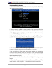
(*Rear View: When viewing it from the
rear side of the system)