


ProtectNet
®
Modular Data Line
Installation Manual
Surge Protection System
Thank you for purchasing APC’s Modular Data Line Surge Protection System. Please fill out the supplied Warranty Registration Card or an on-line Product Warranty Registration form at www.apc.com.
APC’s Modular Data Line Surge Protection System consists of a variety of interchangeable surge suppression modules installed in either a four position “PRM4” or a 24 position “PRM24” chassis with the mounting hardware and ground wire. A list
of the modules that are available, and the types of data lines they protect are provided below. The PRM4 is designed to mount inside a home wiring enclosure. The PRM24 is designed to mount in a standard 19-inch rack enclosure.
This manual provides basic installation information for the PRM4 chassis and associated modules. For PRM24 installation information, reference APC manual 990-1383A.
Note: Procedures provided in this document are not intended to supersede local standards or codes. Reference the Telecommunications Industries Association and Electronic Industries Alliance publication “Commercial Building,
Telecommunications Cabling Standard, General Requirements” (document number TIA/EIA-568-B.1-2001) to ensure the system wiring is installed properly.
Safety
Please read and save these instructions, and observe the following safety precautions.
• Use the system in a protected environment only.
• Never install telephone wiring or coaxial cable during a lightning storm.
• Follow the installation instructions carefully. The current limiting feature of this product could be rendered inoperable if the product is improperly installed.
Caution: This equipment is intended to be used in a restricted access area and should only be worked on by qualified service personal.
w
w
w
.apc.com
®
Other Considerations
• Do not install this device in an environment where the operating temperature exceeds 0 to 40
o
C (32 to 104
o
F).
• Do not install this device where the relative humidity exceeds 95%, non-condensing.
• Do not store this device in an environment that exceeds 0 to 45
o
C (32 to 113
o
F).
Chassis Installation and Grounding
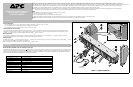
APC recommends that the ProtectNet Data Line Surge Protection chassis ( , Figure 1) PRM24, be installed using the mounting hardware provided with the chassis.
Additionally, the chassis must be connected to a proper protective earth ground. A ground stud is provided on the back of the chassis. Ensure the mounting rack or
enclosure is connected to a proper ground. Install the chassis and modules as shown in Figure 1.
Module Installation
The system chassis is designed to accomodate up to 24 data line modules.To install a module, remove one of the blank panels by pulling it straight out from the
chassis.Align the module with the groove in the chassis, and slide the module fully into the chassis.
Cable Installation
To install a data line cable , connect the input RJ-45 connector to the signal source and then to the upper connector on the module. Connect a data line cable from the
lower connector on the module to the equipment to be protected.
Note: To accomodate 24 modules, the four-wide center blank panel must be removed.
1
2
3
4
5
6 7 8
9
Module Information
Model PNETR5 and PNETR6 (Cat5 and Cat6 Network Protection)
The PNETR5 and PNETR6 modules protect the ports of a
network interface cards, hubs or other local area network (LAN) equipment from damage caused by electrical tran-
sients over a Cat5 or Cat6 data line. These modules provide surge protection for 10Base-T, 100Base-T4, 100Base-TX, 100VG or Token Ring Type 3 UTP port (RJ-45), and
VOIP standards and applications. Both modules comply with IEEE 802.3 and IEEE 802.5. PNETR6 is also compatible with 1000Base-T/Cat6 and IEEE 802.12 Ethernet
standard, Cat5 and Cat6. PNETR5 and PNETR6 key specifications are listed below.
Item Specification
PNETR5/PNETR6 Lines Protected
Pins 1 - 8 on RJ-45 connector
PNETR5/
PNETR6 Mode of Protection
Between send/receive pairs and any signal line to ground.
PNETR5/
PNETR6 Peak Voltage
± 2,000 Volts, 1.2/ 50 µs test waveform
PNETR5 Peak Current 150 Amps, 8/20 µs test waveform
PNETR6 Peak Current 250 Amps, 8/20 µs test waveform
PNETR5 Breakover (turn on) Voltage 60 V peak nominal between send/receive pairs
PNETR6 Breakover (turn on) Voltage 60 Vdc nominal
PNETR5/
PNETR6 Isolation
Both comply with applicable safety isolation requirements of IEEE 802.3 and 802.5.
PNETR6 complies with 802.12 Ethernet Cat5, 6.
PNETR5/
PNETR6 Response Time
<1ns
Agency Approvals UL 497B recognized
6
3
4
8
To Equipment
to be Protected
From Signal
Source
1
7
5
2
9
Figure 1. Typical Installation
Ground
Stud / Wire
General Information