©
National Instruments Corporation 3-1 BNC-2140 User Manual
3
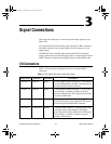
Signal Connections
This chapter describes how to connect input and output signals to your
BNC-2140.
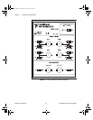
You can connect the external analog signals through six BNC connectors.
Four BNC connectors are for input signals and two connectors are for
output signals.
The SHC68-C68-A1 shielded cable connects the BNC-2140 internal
analog signal connector to the DSA plug-in device. A single 68-pin 0.8 mm
VHDCI connector connects the analog I/O signals to the shielded cable.
I/O Connectors
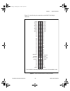
Table 3-1 shows the pin assignments for the six external I/O BNC
connectors.
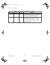
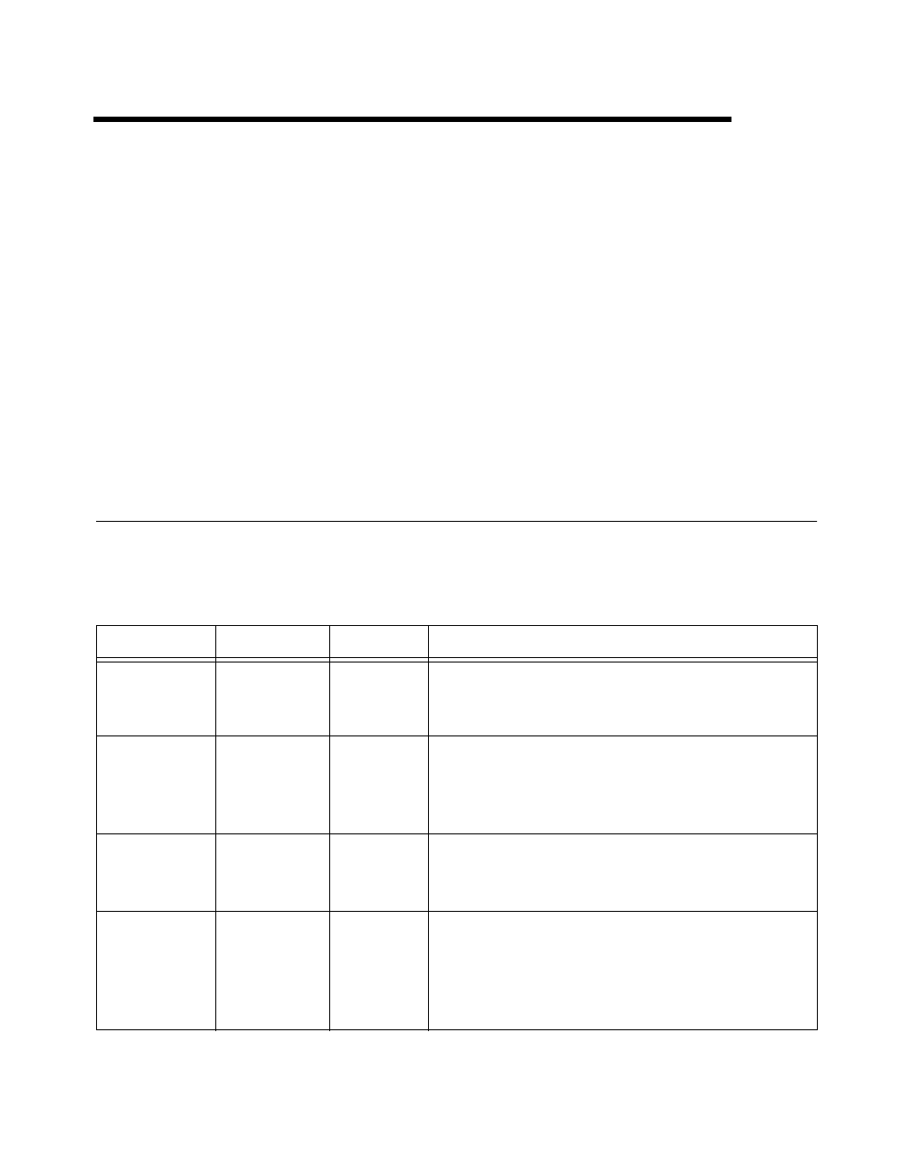
Table 3-1.
BNC Analog I/O Connector Signal Descriptions
Signal Name Reference Direction Description
+ACH<0..3> AIGND Input +Analog Input Channel 0 through 3—Each channel
can have ICP enabled or disabled. This signal passes
through the BNC internal conductor.
–ACH<0..3> AIGND Input
–Analog Input Channel 0 through 3
—
In SE mode
the inverting (–) terminal is tethered to ground
through a 50
Ω
resistor. This signal passes through
the external BNC shell.
+DAC0OUT –DAC0OUT Output +Analog Output Channel 0—This pin supplies the
analog non-inverting output channel 0. This signal
passes through the internal BNC conductor.
–DAC0OUT +DAC0OUT Output
–Analog Output Channel 0
—
This pin supplies the
analog inverting output channel 0. This signal
passes through the external BNC shell. In SE mode,
the inverting (–) terminal is tethered to ground
through a 50
Ω
resistor.
UM.book Page 1 Tuesday, July 14, 1998 10:37 AM