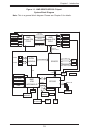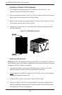
Chapter 5: Advanced Serverboard Setup
5-13
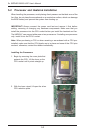
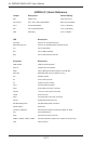
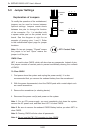
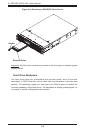
5-8 Connector Denitions
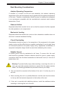
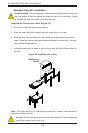
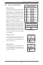
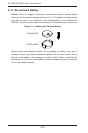
Power Connectors
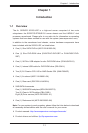
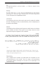
A 20-pin main power supply connector(JPW1)
and two 8-pin CPU PWR connectors
(JPW2/JPW3) on the motherboard. These
power connectors meet the SSI EPS 12V
specication. In addition to the 20-pin ATX
power connector, the 12V 8-pin CPU PWR
connectors at JPW2/JPW3 must also be
connected to your power supply. See the
table on the right for pin denitions.
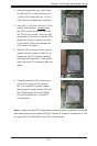
Warning: To prevent damage to the power
supply or motherboard, please use a power
supply that contains a 20-pin and two 8-pin
power connectors. Be sure to connect these
connectors to the 20-pin (JPW1) and the two
8-pin (JPW2,JPW3) power connectors on the
motherboard. Failure in doing so will void the
manufacturer warranty on your power supply
and motherboard.
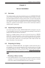
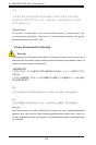
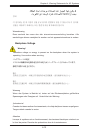
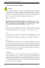
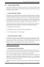
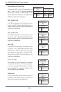
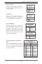
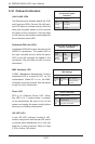
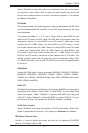
Reset Connector
The reset connector is located on pins 3 and
4 of JF1 and attaches to the reset switch on
the computer chassis. See the table on the
right for pin denitions.
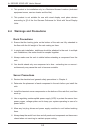
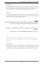
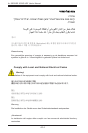
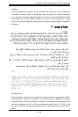
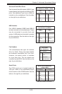
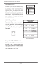
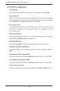
PW_ON Connector
The PW_ON connector is on pins 1 and 2 of
JF1. This header should be connected to the
chassis power button. See the table on the
right for pin denitions.
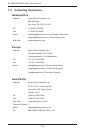
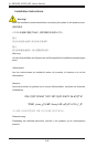
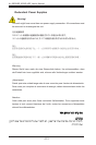
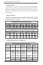
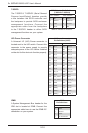
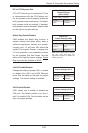
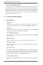
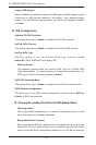
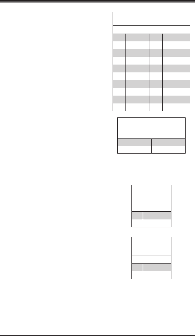
12V 8-pin PWR Connector
Pin Denitions (JPW2/JPW3)
Pins Denition
1 through 4 Ground
5 through 8 +12V
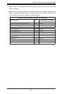
Required Connection
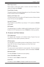
Reset Button
Pin Denitions
(JF1)
Pin# Denition
3 Reset
4 Ground
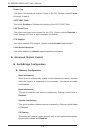
Power Button
Pin Denitions
(JF1)
Pin# Denition
1 PW_ON
2 Ground
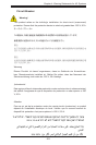
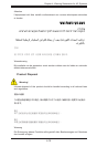
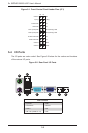
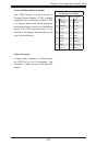
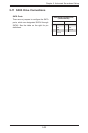
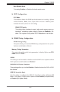
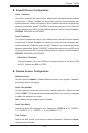
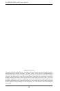
ATX Power 20-pin Connector
Pin Denitions (JPW1)
Pin# Denition Pin # Denition
11 +3.3V 1 +3.3V
12 -12V 2 +3.3V
13 COM 3 COM
14 PS_ON 4 +5V
15 COM 5 COM
16 COM 6 +5V
17 COM 7 COM
18 NC 8 PWR_OK
19 +5V 9 5VSB
20 +5V 10 +12V