5-14
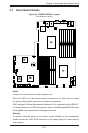
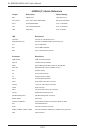
A+ SERVER 2022G-URF User's Manual
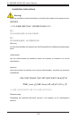
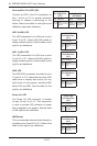
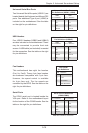
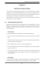
NIC2 (LAN2) LED
The LED connections for LAN2 are on pins
9 and 10 of JF1. Attach LAN LED cables to
display network activity. See the table on the
right for pin denitions.
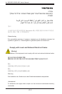
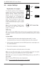
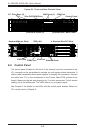
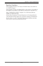
HDD LED
The HDD LED connection is located on pins
13 and 14 of JF1. Attach the hard drive LED
cable here to display disk activity (for any
hard drives on the system, including SAS,
Serial ATA and IDE). See the table on the
right for pin denitions
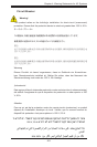
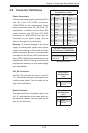
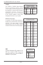
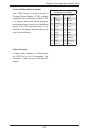
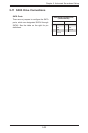
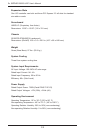
NIC1 LED
Pin Denitions
(JF1)
Pin# Denition
11 Activity
12 Link
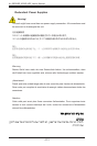
NIC2 LED
Pin Denitions
(JF1)
Pin# Denition
9 Activity
10 Link
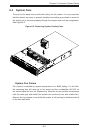
NIC1 (LAN1) LED
The LED connections for LAN1 are on pins
11 and 12 of JF1. Attach LAN LED cables to
display network activity. See the table on the
right for pin denitions.
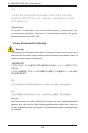
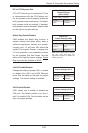
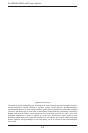
Power On LED
The Power On LED connector is located
on pins 15 and 16 of JF1. This connection
is used to provide LED indication of power
being supplied to the system. See the table
on the right for pin denitions.
Power LED
Pin Denitions
(JF1)
Pin# Denition
15 5V Stby
16 Control
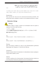
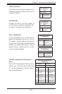
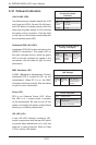
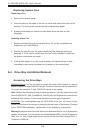
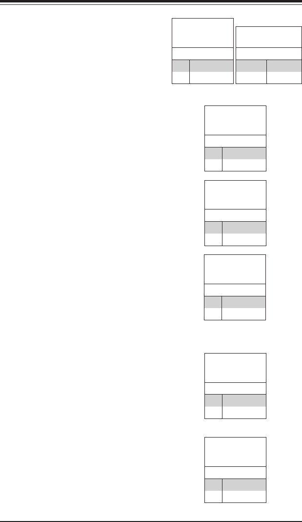
NMI Button
The non-maskable interrupt button header is
located on pins 19 and 20 of JF1. Refer to the
table on the right for pin denitions.
NMI Button
Pin Denitions
(JF1)
Pin# Denition
19 Control
20 Ground
Overheat/Fan Fail LED (OH)
Connect an LED to the OH connection on
pins 7 and 8 of JF1 to provide advanced
warning of chassis overheating or fan
failure. Refer to the table on the right for pin
denitions and status indicators.
OH/Fan Fail LED
Pin Denitions
(JF1)
Pin# Denition
7 Vcc
8 Control
OH/Fan Fail
LED Status
State Indication
Solid Overheat
Blinking Fan fail
HDD LED
Pin Denitions
(JF1)
Pin# Denition
13 Vcc
14 HD Active