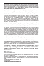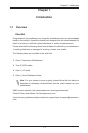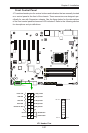
Chapter 2: Installation
2-11
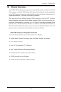
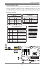
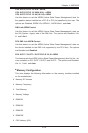
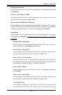
CLR_CMOS_SW
16
JOCE
JHDMI
JUSB01
J37
A-SATA0
I-SATA0
I-SATA1
I-SATA2
LED210 6LED310 6
PCIE3
PCIE5
PCIE1
U103
18 34
51
5268
JPUSB2
1
3
JPUSB1
13
JLED1
1
JVR2
1
3
JPL1
1
JBR1
1
JPME2
1
JPL2
1
JPAC1
13
JPME1
1
3
JWD1
1
3
JVR1
1
3
JBT1
JUSBLAN2
JUSBLAN1
JSTBY1
1
3
3
1
JSD1
DIMM1
DIMM2 DIMM3
DIMM4
+
+
7
2
1
8
7
2
1
T-SGPIO2
JCOM1
1
5
JUSB30_I1
1
19
10
11
11
10
19
1
JUSB30_I
13
JPCIE2 JPCIE6
JPCIE4
J1
RT1
JF1
1
16
J31
DESIGNED IN USA
C7Z87-OCE
REV:1.00
BIOS LICENSE
FOR HOME OR OFFICE USE
With FCC Standards
Tested to Comply
19
20
JTPM1
1
2
JPW2
1
C398
C3491
C401
C582
C591
C592
J38
1
7
10
J1394_1
10
7
2
1
J36
2
J35
7
1
2
10
7
J34
1
1
JPEX_DEBUG
JL1
1
JL2
1
JWOR1
JSPDIF_OUT
1
JI2C1
1
JI2C2
1
24
13
JPW1
1
U197
U196
59
1
JITP1
2
OC3_LED
A
C
C
A
LED1
CATERR_LED
A
C
R743
R154
R155
R156
R298
R97
+
SP1
41
JCHLED1
1
FAN3
4
4
1
FAN2
FAN5
1
4
4
1
FAN1
4
FAN4
1
1
JD1
4
MH5
MH1
MH6
MH8
MH9
MH2
MH3
MH4
MH7
JAUDIO1
THUNDERBOLT
USB 6/7(3.0)
USB 16/17
USB 4/5(3.0)
USB 14/15
USB 2/3(3.0)
USB 0/1(3.0)
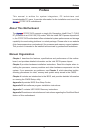
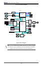
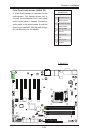
CPU
CPU_SLOT2 PCI-E 3.0 X4 (IN X16)
PCH_SLOT1 PCI-E 2.0 X1 (INX4)
PCH_SLOT5 PCI-E 2.0 X1 (INX4)
PCH_SLOT3 PCI-E 2.0 X1 (INX4)
USB12/13
USB8/9
USB 2/3
LAN2
LAN1
HDMI
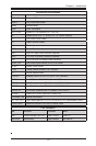
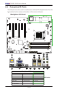
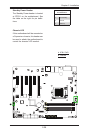
JWD1:
JBR1:
2-3:BIOS RECOVERY
1-2:NORMAL
JPME1:
2-3:ME RECOVERY
1-2:NORMAL
JSD1:
ENABLE
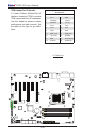
LAN2
DISABLE
2-3
1-2
JPL2
LAN1
DISABLE
ENABLE
2-3
1-2
JPL1
JWOR1:
2-3:NMI
1-2:RST
WATCH DOG
CPU
2-3:ME MANUFACTURING MODE
USB 0/1
1-2:NORMAL
JPME2:
SATA DOM PWR
JTPM1:TPM/PORT80
JL1:
JLED1:
3 PIN POWER LED
AUDIO FP
HDDPWR
LEDLED
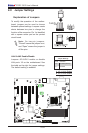
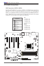
P1-DIMMB1
P1-DIMMB2
NIC1
SPEAKER:1-4
JD1:
BUZZER:3-4
JI2C1/JI2C2
ON:ENABLE
OFF:DISABLE
NIC2
HD AUDIO
WAKE ON RING
USB4/5
USB6/7
OH/FF
LED
X
CHASSIS INTRUSION
P1-DIMMA1
P1-DIMMA2
RST
PWR
JF1
ON
ALWAYS POPULATE BLUE SOCKET FIRST
UNB NON-ECC DDR3 DIMM REQUIRED
CPU_SLOT4 PCI-E 3.0 X8 (IN X16)
CPU_SLOT6 PCI-E 3.0 X16
COM1
VGA/DVI
USB10/11
2-3:DISABLE
1-2:ENABLE
JPAC1:AUDIO
CPU
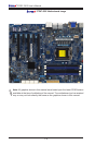
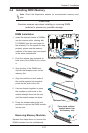
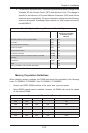
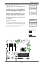
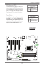
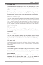
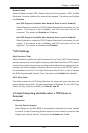
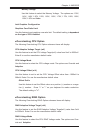
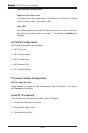
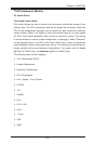
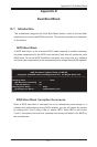
2-4 Installing DDR3 Memory
Note: Check the Supermicro website for recommended memory mod-
ules.
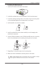
CAUTION
Exercise extreme care when installing or removing DIMM
modules to prevent any possible damage.
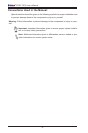
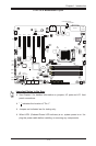
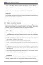
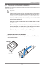
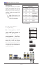
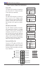
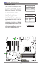
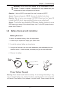
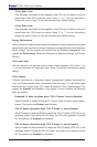
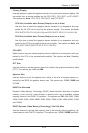
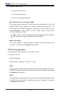
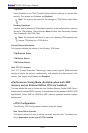
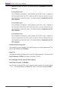
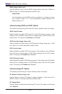
DIMM Installation
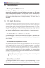
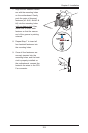
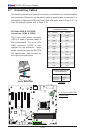
1. Insert the desired number of DIMMs
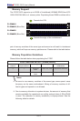
into the memory slots, starting with
P1-DIMMA2 (see the next page for
the location). For the system to work
properly, please use the memory
modules of the same type and speed
in the same motherboard.
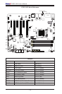
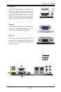
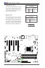
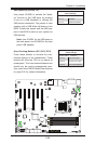
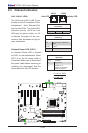
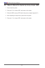
Release Tabs
Notches
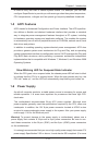
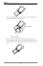
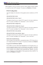
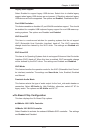
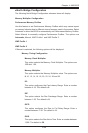
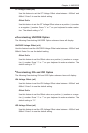
2. Push the release tabs outwards on
both ends of the DIMM slot to unlock
it.
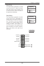
Press both notches
straight down into
the memory slot.
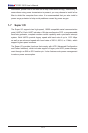
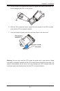
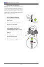
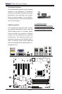
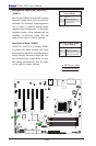
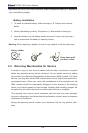
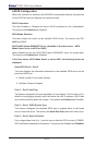
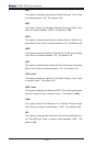
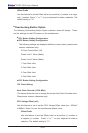
3. Align the key of the DIMM mod-
ule with the receptive point on the
memory slot.
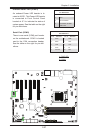
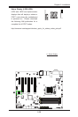
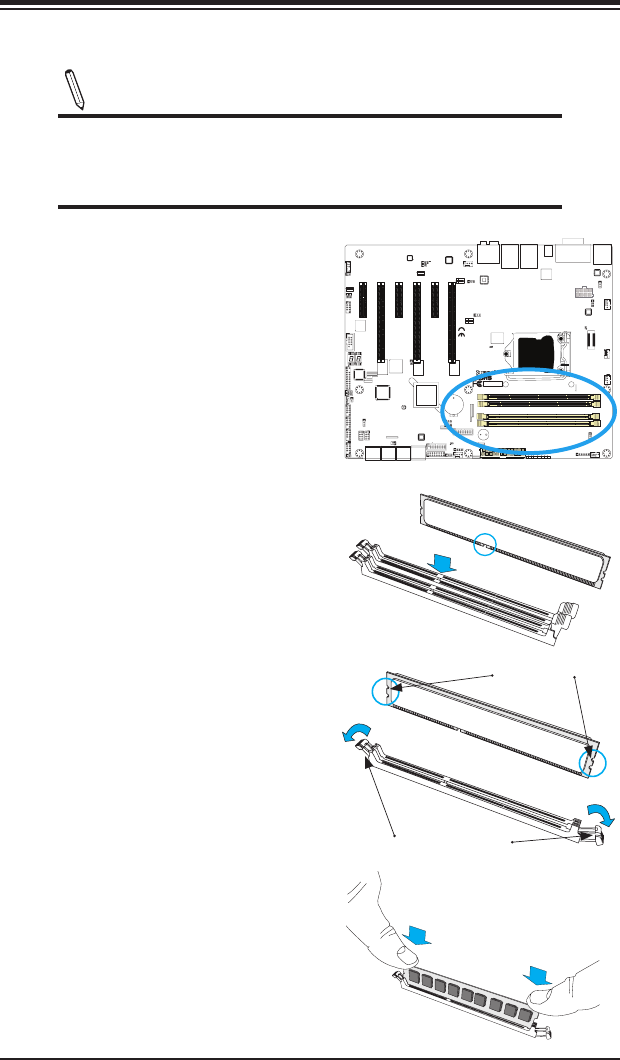
4. Align the notches on both ends of
the module against the receptive
points on the ends of the slot.
5. Use two thumbs together to press
the notches on both ends of the
module straight down into the slot
until the module snaps into place.
6. Press the release tabs to the lock
positions to secure the DIMM module
into the slot.
Removing Memory Modules
Reverse the steps above to remove the
DIMM modules from the motherboard.