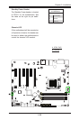
2-22
C7Z87-OCE User’s Manual
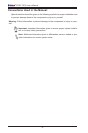
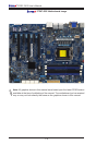
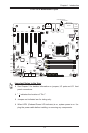
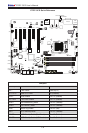
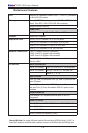
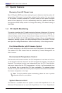
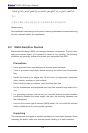
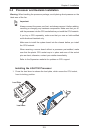
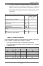
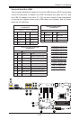
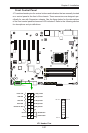
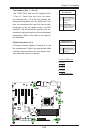
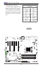
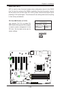
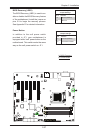
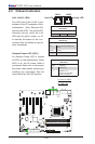
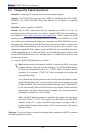
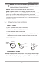
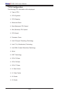
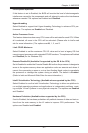
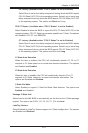
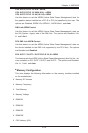
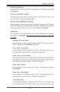
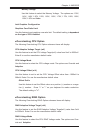
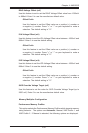
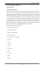
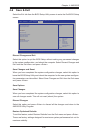
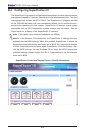
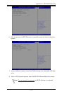
Front Control Panel Pin Denitions
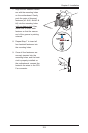
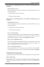
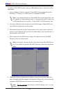
Power LED
The Power LED connection is located on
pins 15 and 16 of JF1. Refer to the table
on the right for pin denitions.
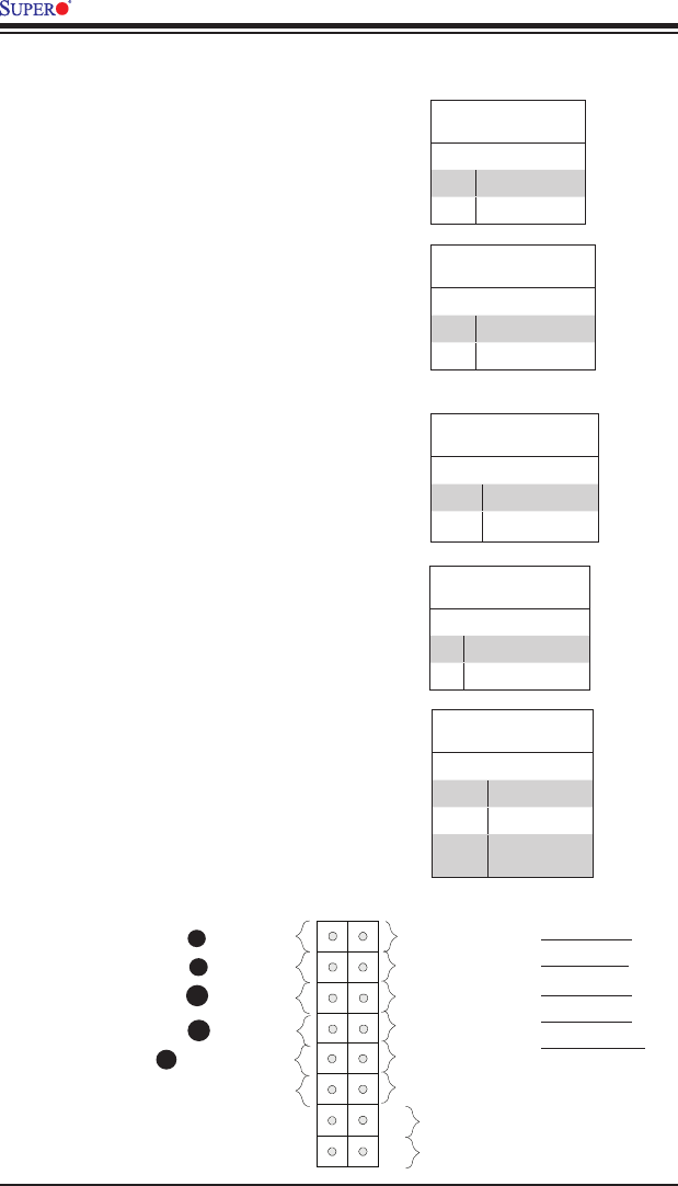
Power LED
Pin Denitions (JF1)
Pin# Denition
15 +5V
16 Ground
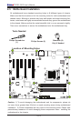
A. PWR LED
B. HDD LED
A
B
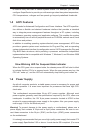
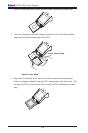
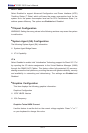
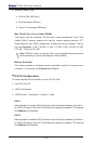
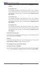
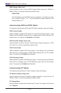
HDD LED
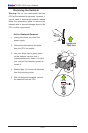
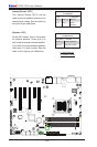
The HDD LED connection is located on
pins 13 and 14 of JF1. Attach a cable
here to indicate the status of HDD-related
activities, including IDE, SATA activities.
See the table on the right for pin deni-
tions.
HDD LED
Pin Denitions (JF1)
Pin# Denition
13 +5V
14 HD Active
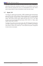
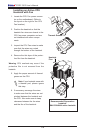
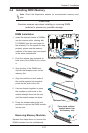
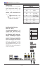
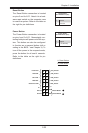
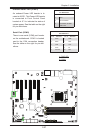
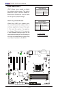
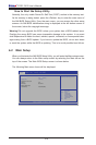
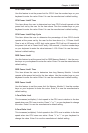
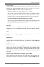
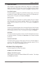
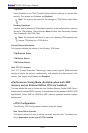
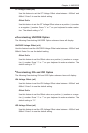
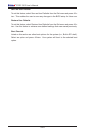
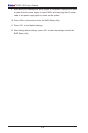
Power Bu
OH/Fan Fail LED
1
NIC1 LED
Reset Butt
2
HDD LED
Power LED
Reset
PWR
LED_Anode+
LED_Anode+
LED_Anode+
LED_Anode+
Ground
Ground
X
X
NIC2 LED
LED_Anode+
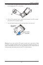
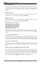
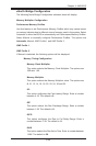
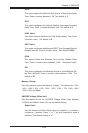
NIC1/NIC2 (LAN1/LAN2)
The NIC (Network Interface Controller)
LED connection for LAN port 1 is located
on pins 11 and 12 of JF1, and the LED
connection for LAN Port 2 is on Pins 9
and 10. NIC1 LED and NIC2 LED are
2-pin NIC LED headers. Attach NIC LED
cables to NIC1 and NIC2 LED indicators
to display network activities. Refer to the
table on the right for pin denitions.
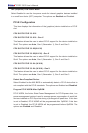
LAN1/LAN2 LED
Pin Denitions (JF1)
Pin# Denition
9/11 Vcc
10/12 Ground
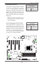
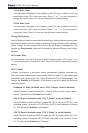
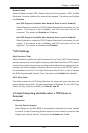
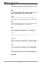
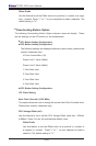
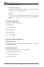
Overheat (OH)/Fan Fail
Connect an LED cable to OH/Fan Fail
connections on pins 7 and 8 of JF1 to
provide warnings for chassis overheat/
fan failure. Refer to the table on the right
for pin denitions.
OH/Fan Fail LED
Pin Denitions (JF1)
Pin# Denition
7 Vcc/Blue UID LED
8 OH/Fan Fail LED
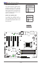
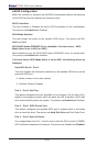
OH/Fan Fail Indicator
Status
State Denition
Off Normal
On Overheat
Flash-
ing
Fan Fail
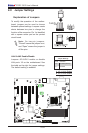
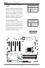
C. NIC1 LED
D. NIC2 LED
E. OH/Fan Fail
C
D
E