H8DI3+/I+(-F) Serverboard User's Manual
2-8
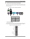
2-7 Connector Defi nitions
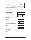
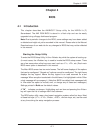
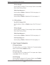
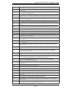
Power Connectors
A 24-pin main power supply connector(JPW1)
and two 8-pin CPU PWR connectors
(JPW2/JPW3) on the serverboard. These
power connectors meet the SSI EPS 12V
specifi cation. In addition to the 24-pin ATX
power connector, the 12V 8-pin CPU PWR
connectors at JPW2/JPW3 must also be
connected to your power supply. See the
table on the right for pin defi nitions.
Warning: To prevent damage to the power
supply or serverboard, please use a power
supply that contains a 24-pin and two 8-pin
power connectors. Be sure to connect these
connectors to the 24-pin (JPW1) and the two
8-pin (JPW2,JPW3) power connectors on the
serverboard. Failure in doing so will void the
manufacturer warranty on your power supply
and serverboard.
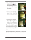
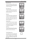
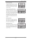
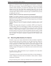
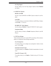
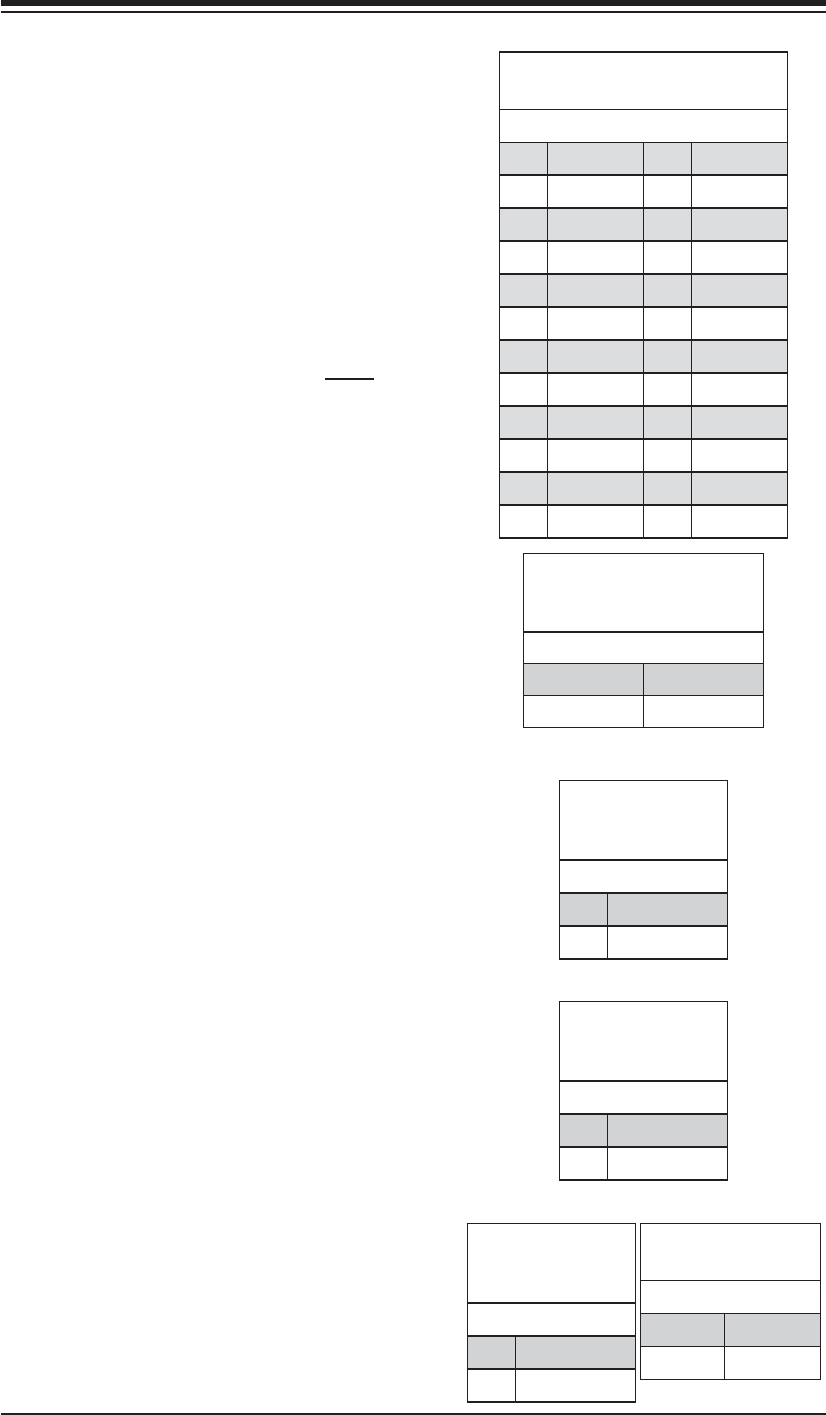
Reset Connector
The reset connector is located on pins 3 and
4 of JF1 and attaches to the reset switch on
the computer chassis. See the table on the
right for pin defi nitions.
PW_ON Connector
The PW_ON connector is on pins 1 and 2 of
JF1. This header should be connected to the
chassis power button. See the table on the
right for pin defi nitions.
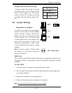
Reset Button
Pin Defi nitions
(JF1)
Pin# Defi nition
3 Reset
4 Ground
Power Button
Pin Defi nitions
(JF1)
Pin# Defi nition
1 PW_ON
2 Ground
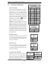
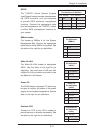
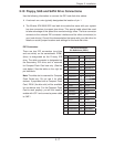
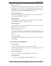
ATX Power 24-pin Connector
Pin Defi nitions
Pin# Defi nition Pin # Defi nition
13 +3.3V 1 +3.3V
14 -12V 2 +3.3V
15 COM 3 COM
16 PS_ON 4 +5V
17 COM 5 COM
18 COM 6 +5V
19 COM 7 COM
20 Res (NC) 8 PWR_OK
21 +5V 9 5VSB
22 +5V 10 +12V
23 +5V 11 +12V
24 COM 12 +3.3V
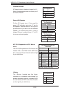
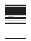
12V 8-pin
PWR Connector
Pin Defi nitions
Pins Defi nition
1 through 4 Ground
5 through 8 +12V
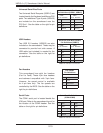
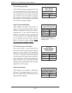
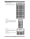
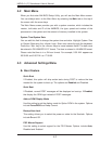
OH/Fan Fail LED
Pin Defi nitions
(JF1)
Pin# Defi nition
7 Vcc
8 Control
OH/Fan Fail
LED Status
State Indication
Solid Overheat
Blinking Fan fail
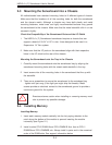
Overheat/Fan Fail LED (OH)
Connect an LED to the OH connection on
pins 7 and 8 of JF1 to provide advanced
warning of chassis overheating or fan
failure. Refer to the table on the right for pin
defi nitions and status indicators.