Chapter 2: Installation
2-11
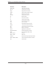
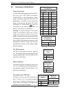
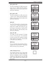
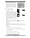
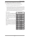
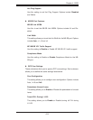
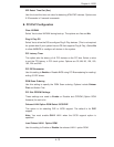
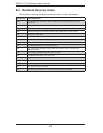
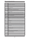
Overheat LED
Connect an LED to the JOH1 header to
provide warning of chassis overheating. See
the table on the right for pin defi nitions.
Overheat LED
Pin Defi nitions
(JOH1)
Pin# Defi nition
1 3.3V
2 OH Active
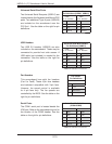
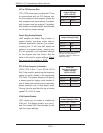
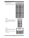
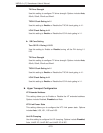
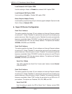
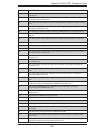
Wake-On-LAN
The Wake-On-LAN header is designated
JWOL. See the table on the right for pin
defi nitions. You must have a LAN card with
a Wake-On-LAN connector and cable to use
the Wake-On-LAN feature.
Wake-On-LAN
Pin Defi nitions
(JWOL)
Pin# Defi nition
1 +5V Standby
2 Ground
3 Wake-up
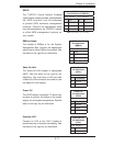
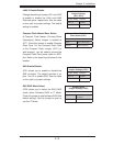
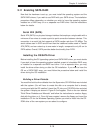
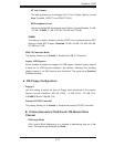
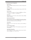
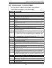
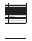
SMBus Header
The header at SMBus is for the System
Management Bus. Connect the appropriate
cable here to utilize SMB on the system. See
the table on the right for pin defi nitions.
SMBus Header
Pin Defi nitions
(SMBus)
Pin# Defi nition
1 Data
2 Ground
3 Clock
4 No Connection
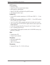
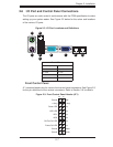
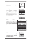
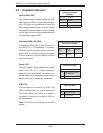
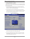
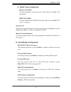
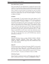
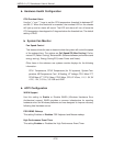
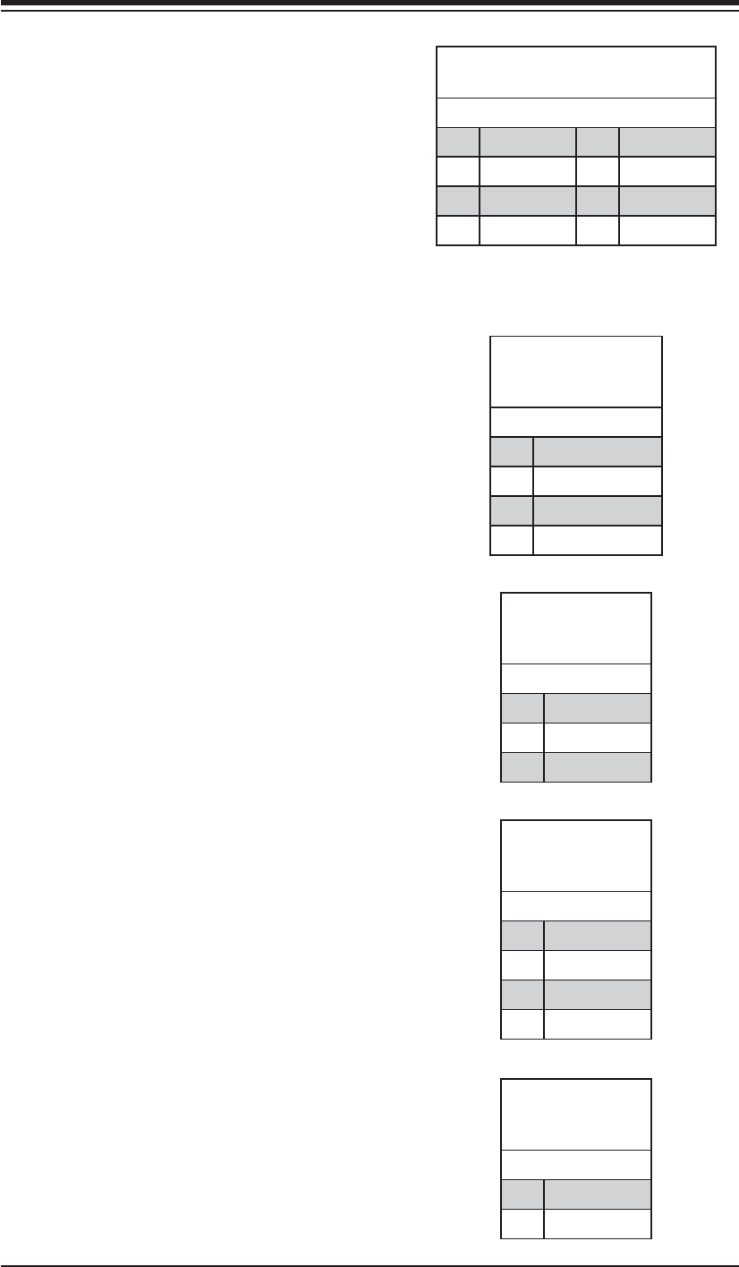
SGPIO
The T-SGPIO1 (Serial General Purpose
Input/Output) header provides a bus between
the SATA controller and the backpane
to provide SATA enclosure management
functions. Connect the appropriate cable
from the backplane to the T-SGPIO1 header
to utilize SATA management functions on
your system.
SGPIO Header
Pin Defi nitions (T-SGPIO1)
Pin# Defi nition Pin # Defi nition
1NC 2NC
3 Ground 4 Data
5 Load 6 Ground
7NC 8NC
Note: NC indicates no connection.
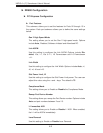
Power I2C
The JPI2C header is for power I
2
C, which may
be used to monitor the status of the power
supply, fan and system temperature. See the
table on the right for pin defi nitions.
Power I
2
C
Pin Defi nitions
(JPI2C)
Pin# Defi nition
1 Data
2 Ground
3 Clock
4NC