Chapter 2: Installation
2-7
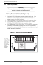
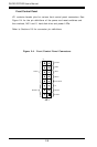
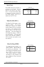
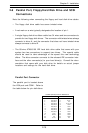
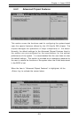
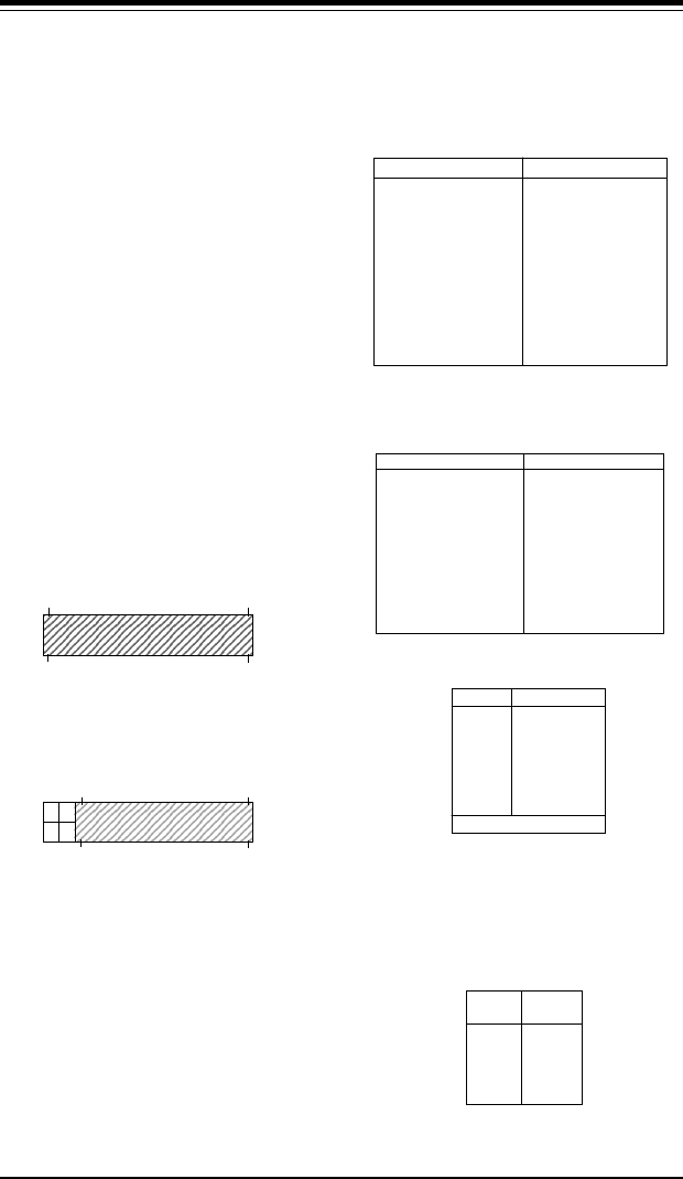
2-6 Connecting Cables
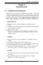
The primary power supply connec-
tor on the P3TDDR meets the SSI
(Superset ATX) 24-pin specifica-
tions, however, it also supports an
ATX 20-pin connector. Refer to
Table 2-1a for pin definitions.
(Also see Figure A below for con-
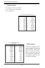
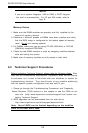
nector orientation). If a 20-pin
connector is used, please refer to
Figure B below for connector ori-
entation and Table 2-1c for stan-
dard wiring colors.
Pin 1
Pin 1
Pin 13
Pin 10
Pin 11
Pin 20
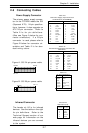
Power Supply Connector
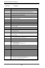
Table 2-1b
ATX Power Supply 20-pin Connector Pin
Definitions
Pin # Definition
11 +3.3V
12 -12V
13 COM
14 PS_ON
15 COM
16 COM
17 COM
18 -5V
19 +5V
20 +5V
Pin # Definition
1 +3.3V
2 +3.3V
3 COM
4 +5V
5 COM
6 +5V
7 COM
8 PW-OK
9 5VSB
10 +12V
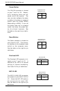
Color Definition
Orange +3.3V
Black Com
Red 5V
White Power OK
Yellow +12V
Purple 5V standby
Brown -5V
(For reference only)
Table 2-1c
PS Color Definitions
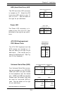
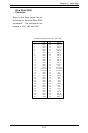
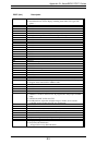
Table 2-1a
ATX Power Supply 24-pin Connector
Pin Definitions (ATX POWER)
Pin Number Definition
13 +3.3V
14 -12V
15 COM
16 PS_ON#
17 COM
18 COM
19 COM
20 Res(NC)
21 +5V
22 +5V
23 +5V
24 COM
Pin Number Definition
1 +3.3V
2 +3.3V
3 COM
4 +5V
5 COM
6 +5V
7 COM
8 PWR_OK
9 5VSB
10 +12V
11 +12V
12 +3.3V
Pin 24
Pin 12
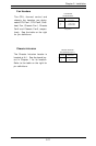
Figure A: SSI 24-pin power cable
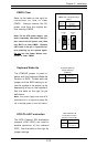
Figure B: SSI 20-pin power cable
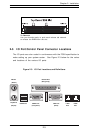
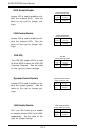
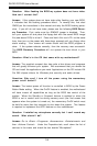
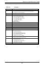
Infrared Connector
The header at J10 is for infrared
devices. See the table on the right
for pin definitions. Refer to the
Technical Support section of our
web page for information on the
infrared devices you can connect
to the system.
Pin
Number
1
2
3
4
5
Definition
+5V
Key
IRRX
Ground
IRTX
Infrared Pin
Definitions (J10)