SUPER P3TDDR User’s Manual
iv
Table of Contents
About This Manual ...................................................................................................... iii
Manual Organization ................................................................................................... iii
Chapter 1: Introduction
1-1 Overview......................................................................................................... 1-1
Checklist .................................................................................................... 1-1
Contacting Supermicro............................................................................ 1-2
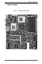
SUPER P3TDDR Image ............................................................................. 1-3
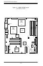
SUPER P3TDDR Layout ........................................................................... 1-4
SUPER P3TDDR Quick Reference .......................................................... 1-5
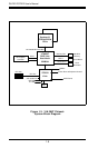
VIA Apollo Pro 266T Chipset: System Block Diagram........................ 1-6
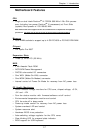
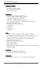
Motherboard Features ............................................................................ 1-7
1-2 Chipset Overview........................................................................................... 1-9
1-3 PC Health Monitoring.................................................................................... 1-10
1-4 ACPI Features ............................................................................................... 1-11
1-5 Power Supply ............................................................................................... 1-13
1-6 Super I/O......................................................................................................... 1-14
Chapter 2: Installation
2-1 Static-Sensitive Devices ............................................................................... 2-1
2-2 Processor Installation .................................................................................... 2-2
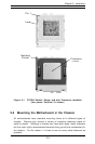
2-3 Mounting the Motherboard in the Chassis ................................................. 2-3
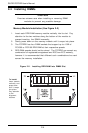
2-4 Installing DIMMs............................................................................................... 2-4
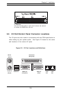
2-5 I/O Port/Front Control Panel Connector Locations.................................... 2-5
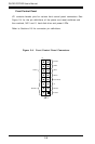
2-6 Connecting Cables ......................................................................................... 2-7
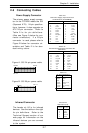
Power Supply Connector ....................................................................... 2-7
Infrared Connector .................................................................................. 2-7
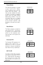
Power Button ............................................................................................ 2-8
Reset Buttonr ........................................................................................... 2-8
Overheat LED ............................................................................................ 2-8
NIC1/2 LED ................................................................................................ 2-8
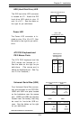
Hard Disk Drive LED ................................................................................. 2-9
Power LED ................................................................................................. 2-9
ATX PS/2 Keyboard/Mouse Ports ......................................................... 2-9
Universal Serial Bus................................................................................ 2-9
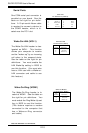
Serial Ports ............................................................................................. 2-10
Wake-On-LAN ......................................................................................... 2-10