2-38
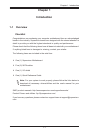
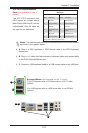
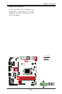
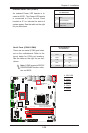
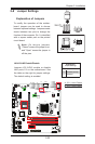
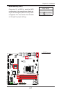
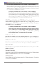
X10SLQ/X10SLQ-L User’s Manual
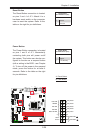
X10SLQ (-L)
Rev. 1.00
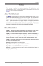
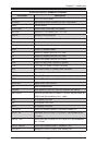
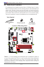
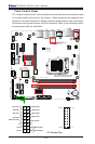
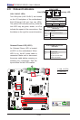
MAC CODE
BAR CODE
BIOS
LICENSE
JSD1
JBT1
SP1
JITP1
LED1
LED2
LED3
T-SGPIO2
COM1
COM2
COM3
COM4
JD1
FAN3
FAN2
FAN1
FAN4
JP2
JP1
JLED1
JWD1
JPL2
JPL1
JPAC1
JI2C1 JI2C2
JP5
JP4
JP3
JL1
JWOR1
JHD_AC1
I-SATA2
I-SATA1
I-SATA3
I-SATA0
I-SATA4
JTPM1
JF1
JPW2
USB10/11(3.0)
AUDIO FP
USB8/9
SLOT4 PCI-E 2.0 X4
SLOT5 PCI-E 2.0 X1
HD AUDIO
SLOT7 PCI-E 3.0 X16
USB4/5
LAN2
USB2/3(3.0)
LAN1
HDMI/DP
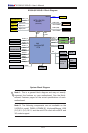
ALWAYS POPULATE BLUE SOCKET FIRST
UNB NON-ECC DDR3 DIMM REQUIRED
VGA/DVI
KB/MOUSE
USB0/1
CPU FAN
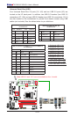
DIMMA1
DIMMA2
DIMMB1
DIMMB2
Battery
JPW1
BIOS
Intel PCH
JBR1
JPME1
JVR1
Not On “-L
Model”
Not On “-L Model”
Not On “-L Model”
Not On “-L
Model”
CPU
Not On “-L Model”
Not On “-L Model”
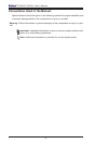
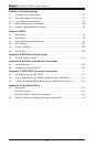
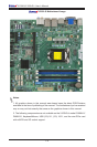
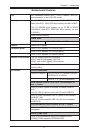
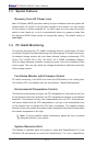
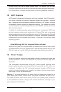
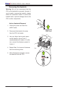
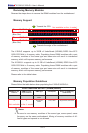
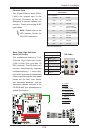
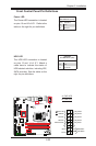
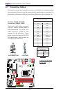
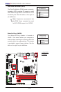
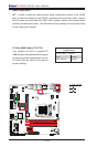
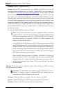
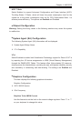
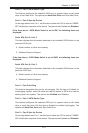
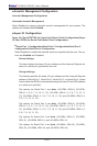
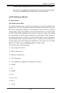
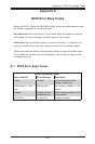
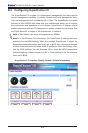
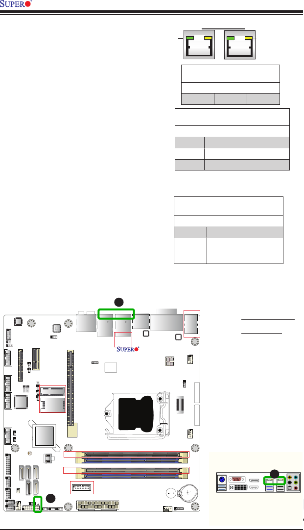
A. LAN 1/2 LEDs
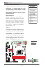
B. PWR LED
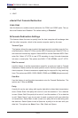
LAN 1/LAN 2 LEDs
Two LAN ports (LAN 1/LAN 2) are located
on the I/O backplane of the motherboard.
Each Ethernet LAN port has two LEDs.
The yellow LED indicates activity, while the
Link LED may be green, amber, or off to
indicate the speed of the connections. See
the tables on the right for more information.
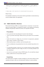
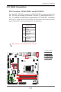
2-9 Onboard Indicators
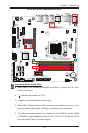
LAN1 LAN2
Activity LED
B
Link LED
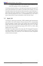
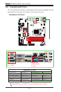
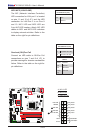
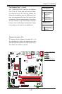
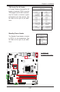
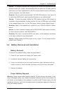
Onboard PWR LED Indicator
LED Status
Status Denition
Off System Off
On System on, or
System off and PWR
Cable Connected
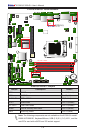
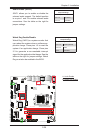
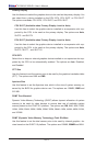
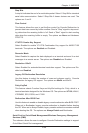
Onboard Power LED (LED1)
An Onboard Power LED is located
at LED1 on the motherboard. When
LED1 is on, the AC power cable is
connected. Make sure to disconnect
the power cable before removing or
installing any component. See the
layout below for the LED location.
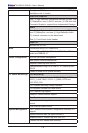
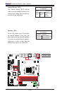
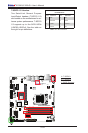
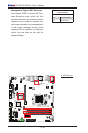
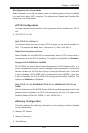
GLAN Ports 1/2 Link Indicator
LED Settings
LED Color Denition
Off No Connection/10 Mbps
Amber 1 Gbps
Green 100 Mbps
GLAN 1/2 Activity Indicator
LED Settings
Color Status Denition
Yellow Flashing Active
A
A