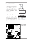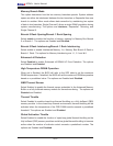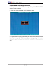
Chapter 2: Installation
2-25
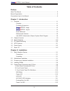
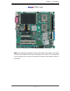
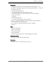
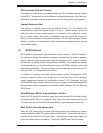
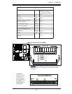
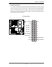
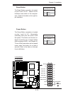
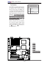
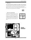
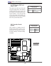
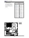
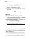
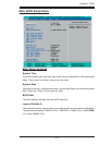
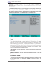
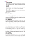
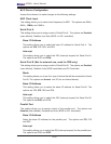
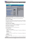
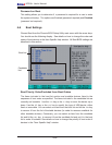
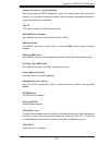
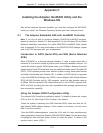
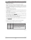
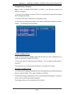
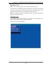
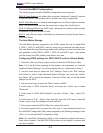
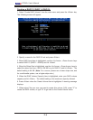
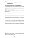
LAN1/2
®
JLAN1
S
UPER X7DA3+
Fan1
8-pin PWR
JF
1
FP Control
SPK
PW LED
JOH1
Fan3
IDE1
Floppy
Fan4
SA
TA3
SA
TA5
USB4/
5
SMB
P
CI-X
100 M
Hz Z
CR
(Green
S
lot
)
P
CI
-X
133
M
H
z
JWD
B
atter
y
G
LAN
C
TL
R
PCI-
Exp x
4
North
Brid
g
e
COM1
Fan
6
Fan
5
A
T
X PWR
4
-Pin
P
WR
J3P
Parrallel
Port
2
4
-Pin
SAS
Controller
P
X
H
CPU1
CP
U
2
South
B
rid
ge
Fan
7
JAR
J17
PSF
JPW2
JPW1
JPW3
Fan2
C
ompa
ct
Flash
LE1
Fan8
J
C
F
1
JWF1
SAT
A
2
SATA4
SA
TA
1
SA
TA
0
JL
1
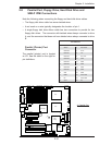
Slot
1
Slot
2
Slot
3
P
CI
-X
133 M
Hz
Slot
4
JPL2
Slot
5
PCI-33MHz
Slot
6
PCI-Exp x16
SIM LP IPMI
Slot
7
D
IMM 1A
(B
an
k 1
)
D
IMM
1B (Ban
k
1)
D
IMM 2A
(B
an
k 2
)
DIMM 2B
(Ban
k
2)
D
IMM 3A
(
B
ank 3)
DIMM 3B
(Bank
3)
D
IMM 4
A
(B
an
k 4
)
D
I
MM
4B
(B
ank
4)
JBT1
J
W
O
L
J
WOR
K
B/
M
ouse
U
S
B
0
/
1/2/3
HD
Audio
J
I
2
C2
J
I
2
C3
J
I
2
C4
G
reencree
k
B
I
OS
CPU
Fan 1
CD1
JPL1
J
I
2
C1
CPU
Fan2
SG
P
IO1
SG
P
IO2
J
S1
0
SAS
4
-
7
SAS0
-
3
JP
S
1
AC
T
0-3
ACT4-
7
Audio
CTRL
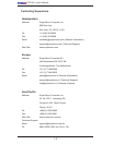
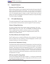
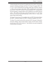
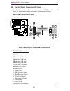
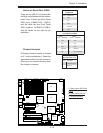
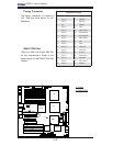
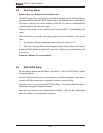
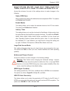
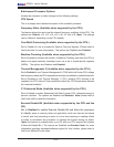
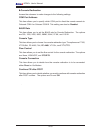
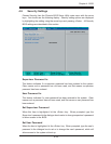
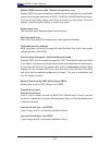
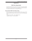
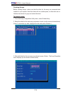
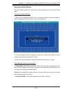
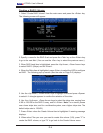
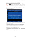
CMOS Clear
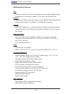
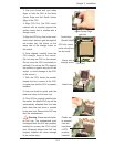
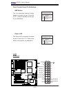
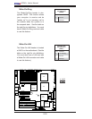
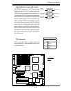
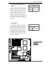
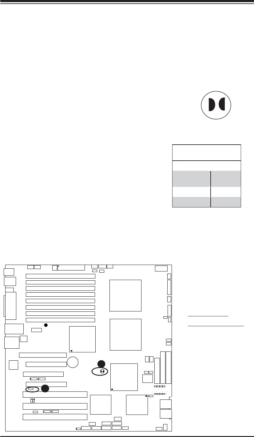
JBT1 is used to clear CMOS. Instead of pins, this "jumper" consists of contact pads
to prevent the accidental clearing of CMOS. To clear CMOS, use a metal object such
as a small screwdriver to touch both pads at the same time to short the connection.
Always remove the AC power cord from the system before clearing CMOS.
Note: For an ATX power supply, you must completely shut down the system, remove
the AC power cord and then short JBT1 to clear CMOS.
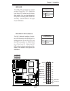
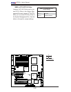
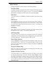
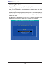
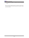
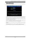
A
B
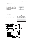
A. Clear CMOS
B. Watch Dog Enable
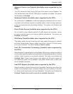
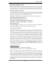
Watch Dog Enable/Disable
Watch Dog is a system monitor that can reboot
the system when a software application hangs.
Close Pins 1-2 to reset the system if an applica-
tion hangs. Close Pins 2-3 to generate a non-
maskable interrupt signal for the application that
hangs. See the table on the right for jumper set-
tings. Watch Dog must also be enabled in the
BIOS.
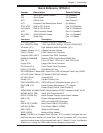
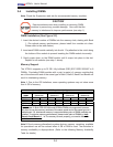
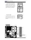
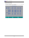
Watch Dog
Jumper Settings (JWD)
Jumper Setting Defi nition
Pins 1-2 Reset
(default)
Pins 2-3 NMI
Open Disabled