Chapter 2: Installation
2-27
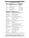
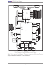
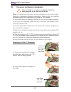
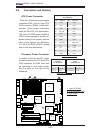
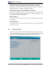
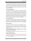
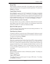
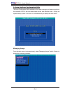
LAN1/2
®
JLAN1
S
UPER X7DA3+
Fan1
8-pin PWR
J
F
1
FP Control
SPK
PW LED
JOH1
Fan3
I
DE1
Floppy
Fan4
SA
TA3
SATA5
USB4/
5
SMB
P
CI-X
100 M
Hz Z
CR
(Green S
lot)
P
CI
-X
133
M
Hz
JWD
B
atter
y
G
L
AN
C
TLR
PCI-
Exp x
4
North
Brid
g
e
COM1
Fan
6
Fan
5
A
T
X PWR
4
-Pin
P
WR
J3P
Parrallel
Port
2
4
-Pin
SAS
Controller
P
X
H
CPU1
CP
U
2
South
B
rid
ge
Fan
7
JAR
J17
PSF
JPW2
JPW1
JPW3
Fan
2
C
ompa
ct
Flash
LE1
Fan8
J
C
F1
JWF1
SATA2
SATA4
SA
TA
1
SA
TA
0
JL
1
Slot
1
Slot
2
Slot
3
P
CI-X
133 M
Hz
Slot
4
JPL2
Slot
5
PCI-33MHz
Slot
6
PCI-Exp x16
SIM LP IPMI
Slot
7
D
I
MM
1
A
(B
an
k 1
)
D
IMM
1B (Ban
k
1)
D
IMM 2A
(B
an
k 2
)
DIMM
2B
(Bank
2)
D
IMM 3A
(B
an
k
3)
DIMM 3B (Bank
3)
D
IMM 4
A
(B
ank 4)
D
I
MM
4B
(B
ank
4)
JBT1
J
WOL
J
WOR
KB/
M
ouse
USB
0
/
1/2/3
HD
Audio
J
I
2
C2
J
I
2
C3
J
I
2
C4
G
reencree
k
B
I
OS
CPU
Fan 1
CD1
JPL1
J
I
2
C1
CPU
Fan2
SG
P
IO1
SG
P
IO2
J
S1
0
SAS
4
-
7
SAS0-3
JP
S
1
AC
T
0-3
ACT4-
7
Audio
CTRL
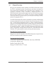
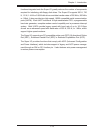
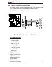
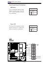
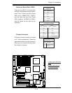
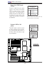
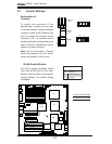
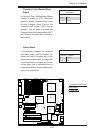
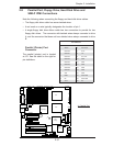
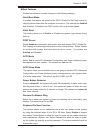
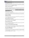
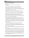
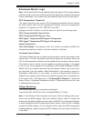
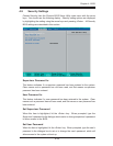
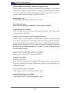
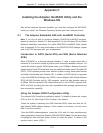
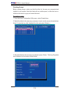
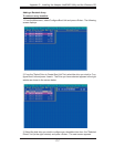
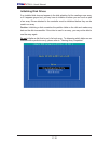
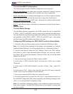
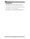
Compact Flash Master/Slave
Select
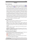
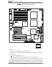
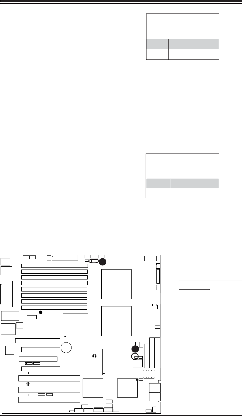
A Compact Flash Master/Slave Select
Jumper is located at JCF1. Close this
jumper to enable Compact Flash Card.
For the Compact Flash Card or the
Compact Flash Jumper (JCF1) to work
properly, you will need to connect the
Compact Flash Card power cable to JWF1
fi rst. Refer to the board layout below for
the location.
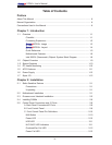
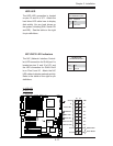
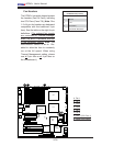
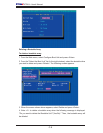
Compact Flash Card Master/
Slave Select
Jumper Defi nition
Open Slave
Closed Master
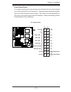
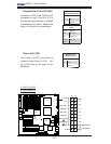
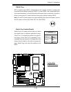
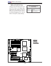
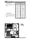
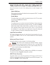
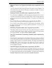
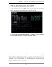
A
B
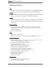
A. Compact Flash Master/
Slave Select
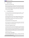
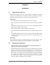
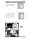
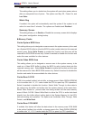
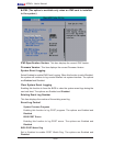
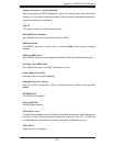
B. Alarm Reset
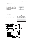
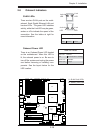
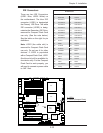
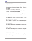
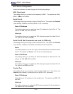
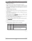
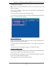
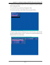
Alarm Reset
If three power supplies are installed
and Alarm Reset (JAR) is enabled, the
system will notify you when any of the
three power modules fails. Connect JAR
to a micro-switch to enable you to turn
off the alarm that is activated when a
power module fails. See the table on the
right for pin defi nitions.
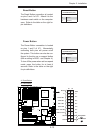
Alarm Reset
Pin Setting Defi nition
Pin 1 Ground
Pin 2 +5V