2-28
X9SPV Motherboard Series User's Manual
1
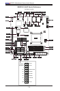
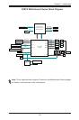
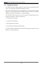
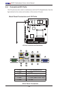
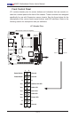
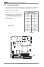
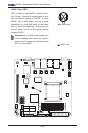
JWD1
UID
VGA
JWP1:WRITE PROTECT
PWR I2C
U60
I-SATA0I-SATA1
JVGA1
JIPMB1
T-SGPIO2T-SGPIO1
JSD1
I-SATA5
I-SATA2
I-SATA4
I-SATA3
J1
J3
F6
JCOM2
J20USB1
SP1
LED2
LED1
LED3
U21
U7
U10
U22
U6
JDIMM1
JDIMM2
JCOM1
FAN2FAN3
FAN1
FAN4
U26
JPW1
JPI2C1
JPK1
U3
JTPM1
JLAN1JLAN2
MH7
MH6
MH2
MH4
JD1
JF1
JP1
JPUSB1
JPB1
JWP1
JL1JOH1
MH4
U57
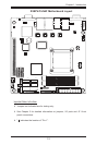
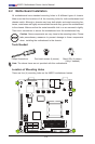
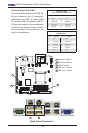
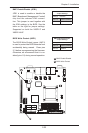
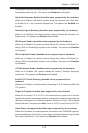
X9SPV-F
JTPM1:TPM/PORT80
DOM POWER
P1-DIMMB1
USB8/9
IPMI
JSD1:SATA
COM2
USB6/7
LAN2/4
LAN1/3
P1-DIMMA1
COM1
USB4/5
KB/MOUSE
A
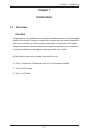
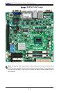
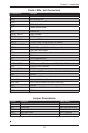
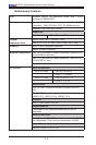
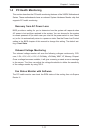
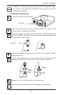
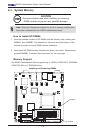
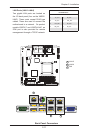
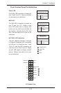
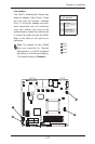
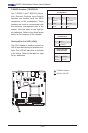
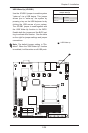
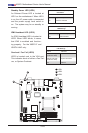
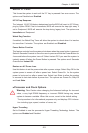
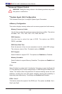
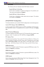
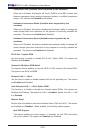
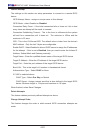
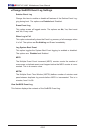
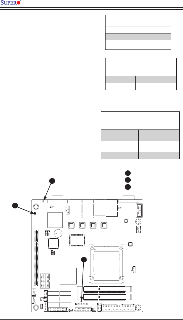
Standby Power LED (LED1)
An Onboard Power LED is located at
LED1 on the motherboard. When LED1
is on, the AC power cable is connected
and the power supply hard switch is
on. The system may be on standby or
running.
Onboard PWR LED (LED1)
LED Status
Status Denition
Off System Off (Soft Switch)
On Power is Detected
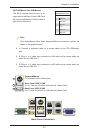
LED1
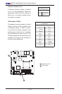
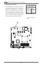
LED2
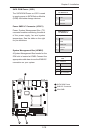
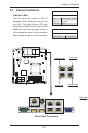
LED3
A
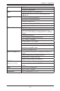
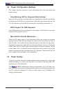
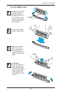
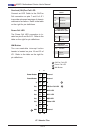
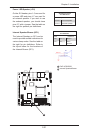
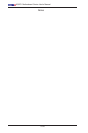
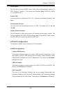
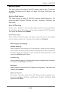
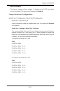
IPMI Heartbeat LED (LED2)
An IPMI Heartbeat LED is located at
LED2. When LED2 blinks, it means
that IPMI is enabled and function-
ing properly. For the X9SPV-F and
X9SPV-LN4F only.
IPMI Heartbeat LED (LED2)
LED Settings
Status Denition
Green: Blinking IPMI is ready for use
Off IPMI Disabled
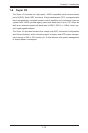
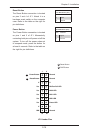
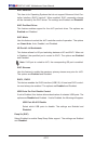
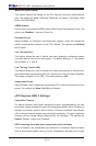
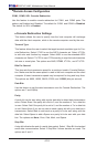
Overheat / Fan Fail (LED3)
LED3 is located next to the VGA port.
This indicator alerts of either a Fan Fail-
ure, or System Overheat.
OH/Fan Fail LED Indicator (LED3)
LED Settings
Status Denition
Yellow: Blinking with
continuous beep
Fan Failure
Yellow: Solid with
continuous beep
System Overheat
Off Normal
B
C
B
C