2-14
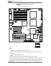
X7DA3+ User's Manual
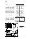
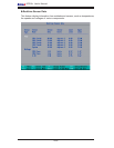
LAN1/2
®
JLAN1
S
UPER X7DA3+
Fan1
8-pin PWR
J
F1
FP Control
SPK
PW LED
JOH1
Fan3
I
DE1
Flopp
y
Fan4
SA
TA3
SATA5
USB4/
5
SMB
P
CI-X
100 M
Hz Z
CR
(Green
S
lot)
P
CI
-X
133
M
Hz
JWD
B
atter
y
G
L
AN
C
TLR
PCI-
Exp x
4
North
Brid
g
e
COM1
Fan
6
Fan
5
A
T
X PWR
4
-Pin
P
WR
J3P
Parrallel
Port
2
4
-Pin
SAS
Controller
P
X
H
CPU1
CP
U
2
South
B
rid
ge
Fan
7
JAR
J17
PSF
JPW2
JPW1
JPW3
Fan
2
C
ompa
ct
Flash
LE1
Fan8
J
C
F1
JWF1
SATA2
SATA4
SA
TA
1
SA
TA
0
JL
1
Slot
1
Slot
2
Slot
3
P
CI-X
133 M
Hz
Slot
4
JPL2
Slot
5
PCI-33MHz
Slot
6
PCI-Exp x16
SIM LP IPMI
Slot
7
D
I
MM
1
A
(B
an
k 1
)
D
IMM
1B (Ban
k
1)
D
IMM 2A
(B
an
k 2
)
DIMM
2B
(Bank
2)
D
IMM 3A
(B
an
k
3)
DIMM 3B (Bank
3)
D
IMM 4
A
(B
ank 4)
D
I
MM
4B
(B
ank
4)
JBT1
J
WOL
J
WOR
KB/
M
ouse
USB
0
/
1/2/3
HD
Audio
J
I
2
C2
J
I
2
C3
J
I
2
C4
G
reencree
k
B
I
OS
CPU
Fan 1
CD1
JPL1
J
I
2
C1
CPU
Fan2
SG
P
IO1
SG
P
IO2
J
S1
0
SAS
4
-
7
SAS0-3
JP
S
1
AC
T
0-3
ACT4-
7
Audio
CTRL
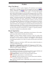
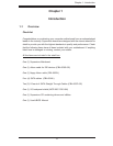
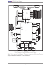
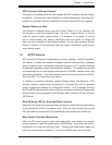
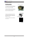
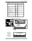
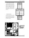
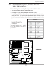
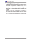
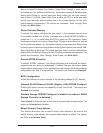
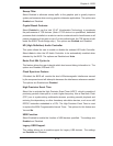
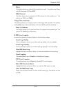
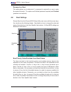
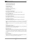
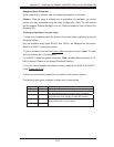
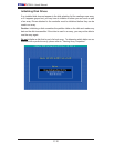
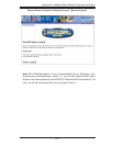
2-6 Connectors and Headers
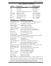
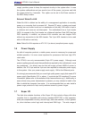
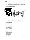
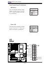
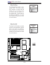
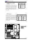
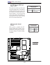
ATX Power Connector
There are a 24-pin main power supply
connector(JPW1) and an 8-pin CPU
PWR connector (JPW3) on the moth-
erboard. These power connectors
meet the SSI EPS 12V specifi cation.
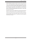
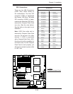
The 4-pin 12V PWR supply located at
JPW2 is also required to provide ad-
equate power to the system. See the
table on the right for pin defi nitions.
For the 8-pin PWR (JPW3), please
refer to the item listed below.
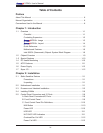
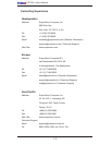
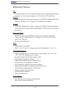
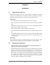
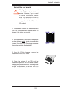
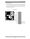
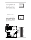
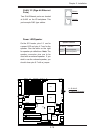
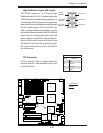
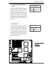
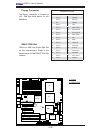
Processor Power Connector
In addition to the Primary ATX power
connector (above), the 12V 8-pin CPU
PWR connector at JPW3 must also
be connected to your power supply.
See the table on the right for pin
defi nitions.
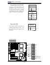
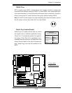
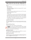
ATX Power 24-pin Connector
Pin Defi nitions
Pin# Defi nition Pin # Defi nition
13 +3.3V 1 +3.3V
14 -12V 2 +3.3V
15 COM 3 COM
16 PS_ON 4 +5V
17 COM 5 COM
18 COM 6 +5V
19 COM 7 COM
20 Res (NC) 8 PWR_OK
21 +5V 9 5VSB
22 +5V 10 +12V
23 +5V 11 +12V
24 COM 12 +3.3V
Required Connection
Required Connection
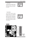
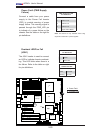
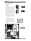
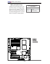
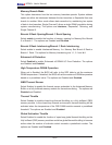
12V 4-pin Power
Connector
Pin Defi nitions
Pins Defi nition
1 and 2 Ground
3 and 4 +12V
12V 8-pin Power Con-
nector
Pin Defi nitions
Pins Defi nition
1 through 4 Ground
5 through 8 +12V
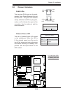
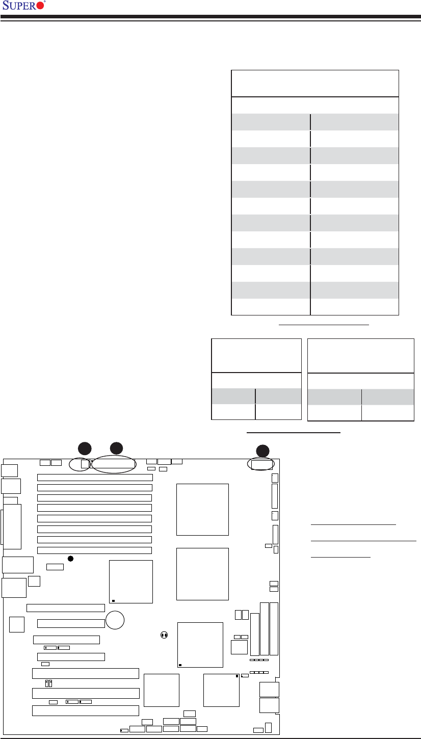
A. 24-pin ATX PWR
B. 8-pin Processor PWR
C. 4-pin PWR
A
B
C