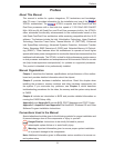
Chapter 2: Installation
2-23
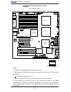
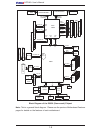
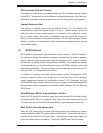
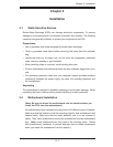
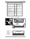
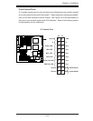
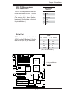
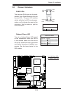
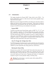
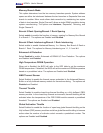
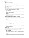
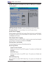
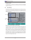
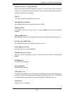
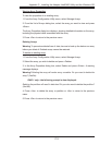
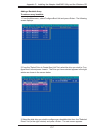
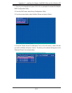
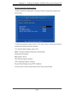
LAN1/2
®
JLAN1
S
UPER X7DA3+
Fan1
8-pin PWR
JF
1
FP Control
SPK
PW LED
JOH1
Fan3
I
DE1
Flopp
y
Fan4
SA
TA3
SAT
A
5
USB4/
5
SMB
P
CI-X
100 M
Hz Z
CR
(Green S
lot)
P
CI
-X
133
M
Hz
JWD
B
atter
y
G
L
AN
C
TLR
PCI-
Exp x
4
North
Brid
g
e
COM1
Fan
6
Fan
5
A
T
X PWR
4
-Pin
P
WR
J3P
Parrallel
Port
2
4
-Pin
SAS
Controller
PX
H
CPU1
CP
U
2
South
B
rid
ge
Fan
7
JAR
J17
PSF
JPW2
JPW1
JPW3
Fan
2
C
ompact Flas
h
LE1
Fan8
J
C
F1
JWF1
SATA2
SATA4
SA
TA
1
SA
TA
0
JL
1
Slot
1
Slot
2
Slot
3
P
CI-X
133 M
Hz
Slot
4
JPL2
Slot
5
PCI-33MHz
Slot
6
PCI-Exp x16
SIM LP IPMI
Slot
7
D
I
MM
1
A
(B
an
k 1
)
D
IMM
1B (Ban
k
1)
D
IMM 2A
(B
an
k 2
)
DIMM
2B
(Bank
2)
D
IMM 3A
(B
an
k
3)
DIMM 3B (Bank
3)
D
IMM 4
A
(B
ank 4)
D
I
MM
4B
(B
ank
4)
JBT1
J
WOL
J
WOR
KB/
M
ouse
USB
0
/
1/2/3
HD
Audio
J
I
2
C2
J
I
2
C3
J
I
2
C4
G
reencree
k
B
I
OS
CPU
Fan 1
CD1
JPL1
J
I
2
C1
CPU
Fan2
SG
P
IO1
SG
P
IO2
J
S1
0
SAS
4
-
7
SAS0-3
JP
S
1
AC
T
0-3
ACT4-
7
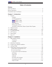
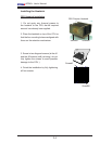
Audio
CTRL
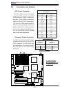
A
B
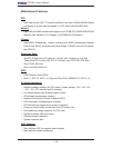
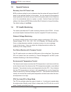
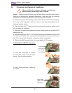
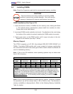
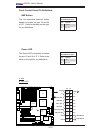
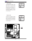
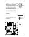
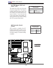
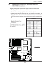
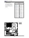
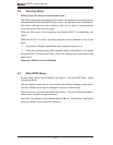
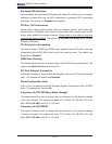
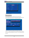
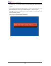
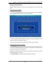
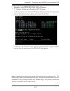
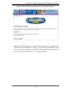
A. HD Audio
B. CD1
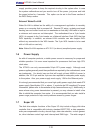
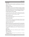
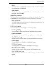
CD Connector
A CD connectors (CD1) is located below the
memory modules. See the tables on the right
for pin defi nitions.
CD1 Pin Defi nition
Pin# Defi nition
1Left
2 Ground
3 Ground
4 Right
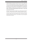
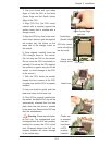
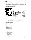
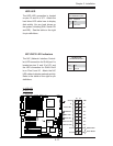
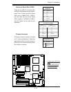
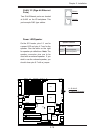
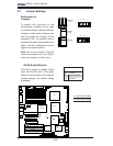
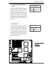
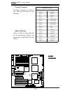
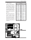
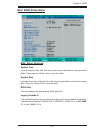
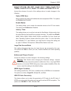
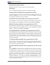
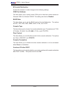
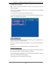
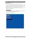
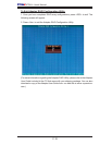
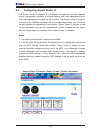
High Defi nition Audio (HD Audio)
The X7DA3+ features a 7.1+2 Channel High
Defi nition Audio (HDA) (JC1) codecs that provide
10DAC channels, simultaneously supporting 7.1
sound playback with 2 channels of independent
stereo sound output (multiple streaming) through
the front panel stereo out (for front L&R, rear
L&R), center and subwoofer speakers. Use the
advanced software included in the CD-ROM that
came with your motherboard and enable the
Audio settings in the BIOS to use this feature.
Sound is then output through the Line In, Line
Out and MIC jacks (see the graphics at right).
Be sure to enable this function in the BIOS to
use this feature.
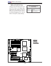
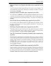
Grey: Side
Surround
Black: Back
Surround
Orange:
CEN/LFE
Pink: Mic-In
Green:Front
Blue: Line-In