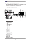
2-12
C2SEA/C2SEE User's Manual
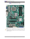
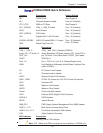
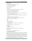
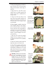
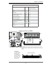
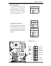
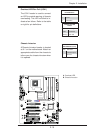
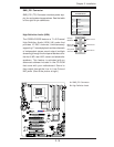
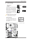
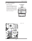
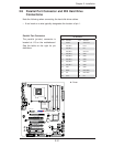
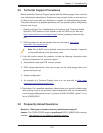
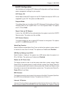
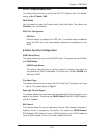
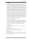
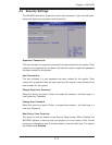
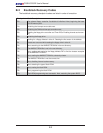
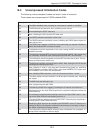
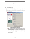
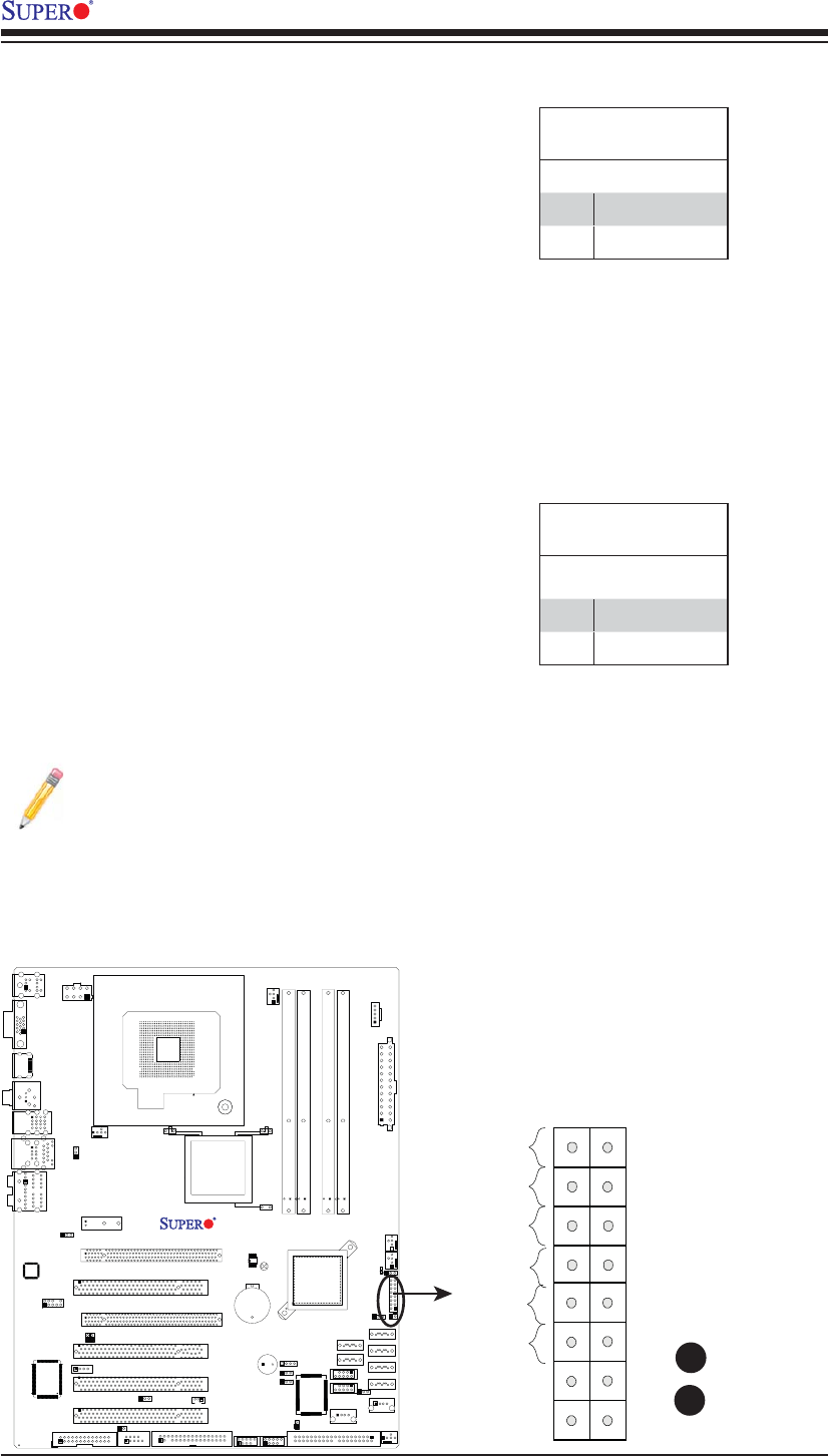
Power Button
OH/Fan Fail LED
NIC1 LED
Reset Button
HDD LED
Power LED
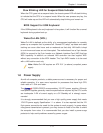
LED_Anode+
LED_Anode+
LED_Anode+
LED_Anode+
Ground
Ground
X
X
LED_Anode+
1516
X
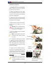
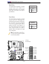
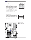
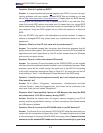
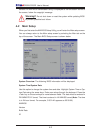
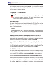
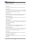
Power Button
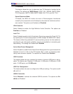
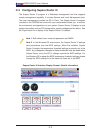
The Power Button connection is located
on pins 1 and 2 of JF1. Momentarily con-
tacting both pins will power on/off the sys-
tem. This button can also be confi gured
to function as a suspend button (with a
setting in the BIOS - see Chapter 4). To
turn off the power when set to suspend
mode, press the button for at least 4
seconds. Refer to the table on the right
for pin defi nitions.
Note: Do not close or short Pins 1
& 2 since this will cause the system
to continuously reboot.
Power Button
Pin Defi nitions (JF1)
Pin# Defi nition
1 Signal
2 +3V Standby
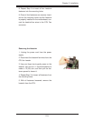
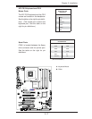
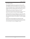
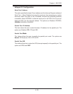
Reset Button
The Reset Button connection is located
on pins 3 and 4 of JF1. Attach it to a
hardware reset switch on the computer
case. Refer to the table on the right for
pin defi nitions.
Reset Button
Pin Defi nitions (JF1)
Pin# Defi nition
3 Reset
4 Ground
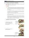
A. Reset
B. PWR Button
A
B
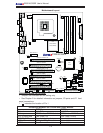
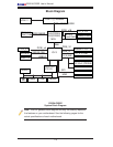
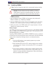
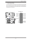
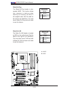
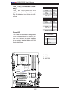
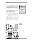
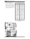
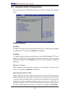
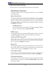
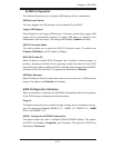
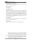
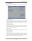
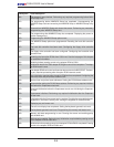
JL1
JI2C1
JI2C2
JOH1
JPUSB1
JPI1
JWD1
JPL1
JPAC
JLED1
JPD1
COM1
JPW1
Floopy
JPW2
JWOL1
SMBUS_PS1
DIMM1
DIMM2
CD1
JBT1
SPKR1
LE1
JD1
Fan5
Fan4
Fan1
Fan3
Fan2
LAN1
JPUSB2
DIMM2B
DIMM4
DIMM3
USB 10/11
USB 8/9
USB6
1394_2
Slot7 PCI-E x1
Slot6 PCI-E Gen2 x16
Slot3 PCI 33MHz
HD AUDIO
JWOR
CPU
CPU Fan
FP Audio
1394_1
CMOS CLEAR
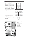
C2SEA/C2SEE
IDE
VGA
HDMI
USB/0/1
I-SATA3
I-SATA2
I-SATA1
I-SATA0
Slot1 PCI 33MHz
Slot5 PCI 33MHZ
Slot4 PCI-E x4 on x16
KB/MOUSE
SPI BIOS
Slot2 PCI 33MHz
DIMM2A
DIMM1B
DIMM1A
USB7
JF1
USB2/3/4/5
SPDIF_Out
Printer
I-SATA4
I-SATA5
Battery
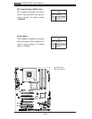
Intel
G45 (C2SEA)
G43 (C2SEE)
ICH10
Intel
Lan
CTRL
S I/O
IDE
CTRL