2-26
X9SCM-IIF/X9SCL-IIF Series User's Manual
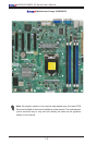
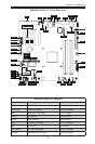
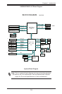
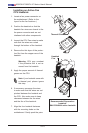
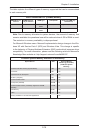
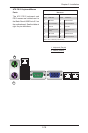
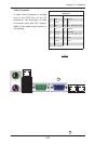
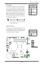
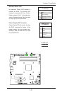
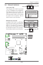
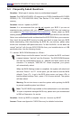
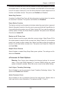
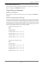
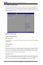
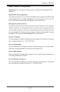
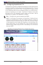
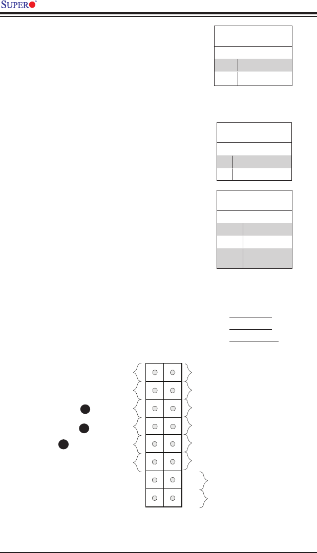
NIC1/NIC2 (LAN1/LAN2)
The NIC (Network Interface Controller)
LED connection for LAN port 1 is located
on pins 11 and 12 of JF1, and the LED
connection for LAN Port 2 is on Pins 9 and
10. NIC1 LED and NIC2 LED are 2-pin
NIC LED headers. Attach NIC LED cables
to the NIC1 and NIC2 LED indicators to
display network activity. Refer to the table
on the right for pin denitions.
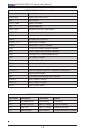
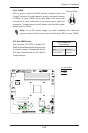
LAN1/LAN2 LED
Pin Denitions (JF1)
Pin# Denition
9/11 Vcc
10/12 LAN Active
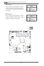
A. NIC1 LED
B. NIC2 LED
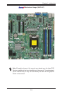
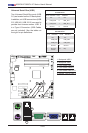
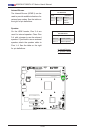
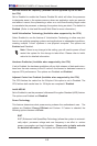
C. OH/Fan Fail
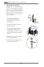
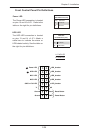
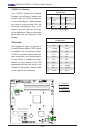
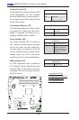
Overheat (OH)/Fan Fail/Front
Connect an LED cable to the OH/Fan
Fail connections on pins 7 and 8 of JF1
to display advanced warnings for chassis
overheat/fan failure. Refer to the table on
the right for pin de nitions.
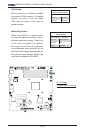
OH/Fan Fail LED
Pin Denitions (JF1)
Pin# Denition
7 Vcc/Blue UID LED
8 OH/Fan Fail LED
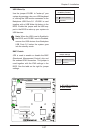
OH/Fan Fail Indicator
Status
State Denition
Off Normal
On Overheat
Flash-
ing
Fan Fail
C
A
B
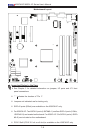
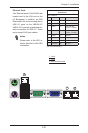
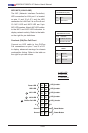
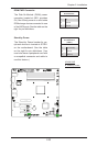
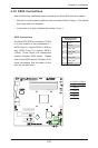
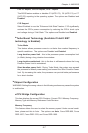
Power Button
OH/Fan Fail LED
1
NIC1 LED
Reset Button
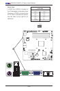
2
HDD LED
Power LED
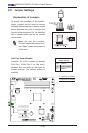
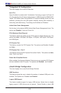
Reset
PWR
LED_Anode+
LED_Anode+
LED_Anode+
Ground
Ground
X
NIC2 LED
LED_Anode+
X
LED_Anode+