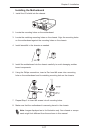
Chapter 2: Installation
2-37
1
1
JI2C2
JI2C1
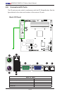
SLOT4 PCI-E 2.0 X4 ON X8
U3
U4
JS2
JS1
J31
JTPM
JPME2
JPME1
J29
JL1
T-SGPIO2
T-SGPIO1
JWF1
JPW2
JWOL
J12
JSPK
JPI2C
JF1
JPW1
B1
JS6
JS3JS4
JS5
J24
JLAN2
JLAN1
COM1
SPKR1
LE3
LE4
LE2
JWD
JLED
JPL2
JPG1
JPBJPL1
JPUSB1
FANA
FAN1
FAN4
FAN3
FAN2
U82
DIMM2
DIMM3
DIMM1
DIMM4
LE7
FF
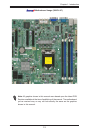
DDR3 1066/1333 UDIMM required
GND
GND
5V
1-2:RST
2-3:NMI
JWD
USB4/5
USB 12/13
_LAN
IPMI
1-2:ENABLE
2-3:DISABLE
JPL2:LAN2
JPL1:LAN1
2-3:DISABLE
1-2:ENABLE
JPB:BMC
JSPK:Buzzer/Speaker
COM2
VGA
COM1
USB11
JBT1:CMOS CLEAR
SLOT7 PCI-E 2.0 X8
LAN2
LAN1
JPUSB1:B/P USB WAKE UP
1-2:ENABLE
2-3:DISABLE
DIMM2B
DIMM2A
JI2C1/JI2C2
USB2/3
SLOT6 PCI-E 2.0 X8
2-3:Disable
1-2:Enable
CPU
JLED1:3 pin Power LED
OFF:Disable
ON:Enable
2-3:DISABLE
1-2:ENABLE
JF1
ON
LED
LED
PWR
HDD
NIC1
NIC2
OH/
X
RST
PWR
USB/0/1
I-SATA3
I-SATA4
I-SATA2
I-SATA1
I-SATA0
I-SATA5
SLOT5 PCI-E 2.0 X4 ON X8
KB/MOUSE
DIMM1B
DIMM1A
JPG1: VGA
JWF1:DOM PWR
JL1:CHASSIS INTRUSION
JBT1
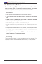
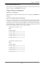
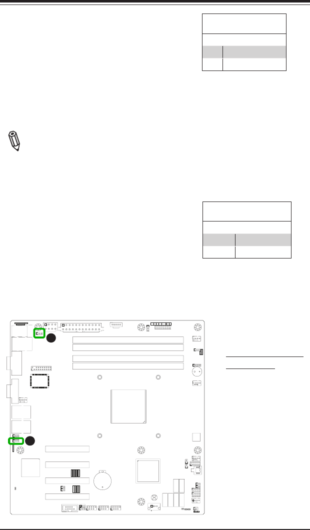
A
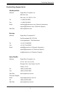
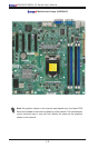
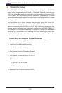
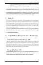
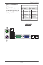
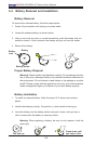
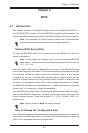
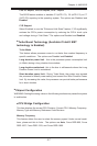
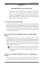
A. BP USB 0/1 Wake-up
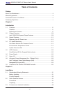
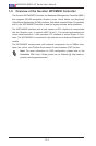
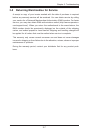
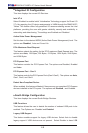
B. BMC Enable
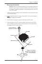
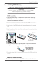
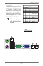
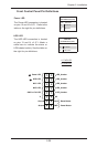
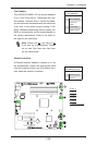
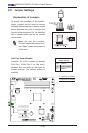
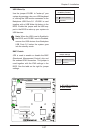
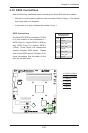
USB Wake-Up
Use the jumper JPUSB1 to "wake-up" your
system by pressing a key on a USB keyboard
or clicking the USB mouse connected to the
Backplane USB Ports 0/1. JPUSB1 is used
together with a USB Wake-Up feature in the
BIOS. Enable this jumper and the USB sup-
port in the BIOS to wake up your system via
USB devices.
Note: When the USB is set to Enabled in
the BIOS, and JPUSB1 is set to Disabled,
remove the USB devices from Backplane
USB Ports 0/1 before the system goes
into the standby mode.
JPUSB1 (Backplane USB
0/1 Wake-up Enable)
Pin# Denition
1-2 Enabled (Default)
2-3 Disabled
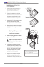
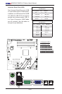
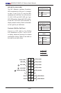
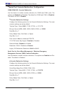
B
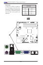
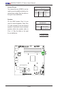
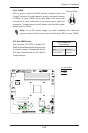
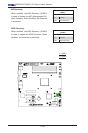
BMC Enable
JPB is used to enable or disable the BMC
(Baseboard Management Control) chip and
the onboard IPMI connection. This jumper is
used together with the IPMI settings in the
BIOS. See the table on the right for jumper
settings.
BMC IPMI Enable/Disable
Jumper Settings
Settings Denition
Pins 1-2 Enabled (Default)
Pins 2-3 Disabled