44
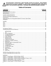
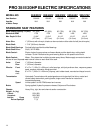
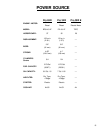
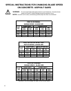
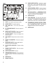
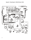
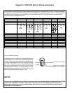
This equipment includes the electric Motor, Motor overload protection, and Motor control circuit. For correct operation,
the equipment must be selected and configured for each voltage and horsepower rating as shown in the following table.
Inspection and/or changes to the equipment are to be performed only after the electrical service has been discon-
nected and then by qualified personnel.
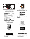
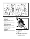
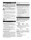
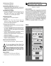
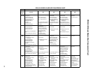
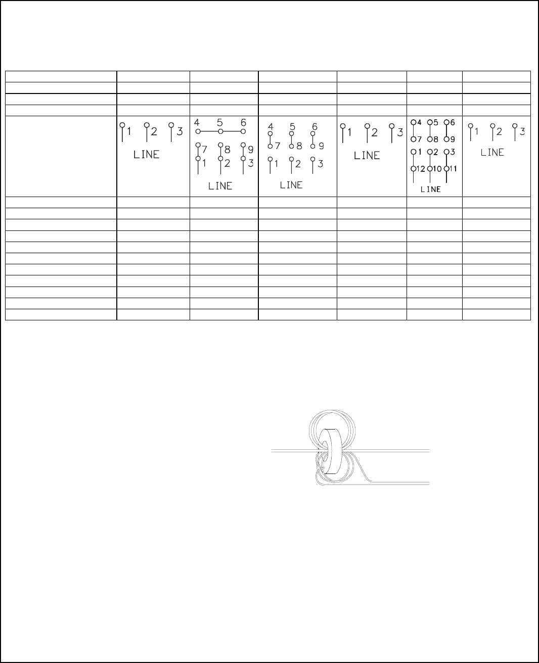
Current Transformer Wiring
A single primary turn is made with a single pass of the red
wire through the hole in the transformer, entering from the
‘H1’ side. Two primary turns are made by passing the red
wire through the transformer hole twice, resulting in a single
loop. The -2 secondary turns are made by passing the
white wire of the transformer through the hole two times
from opposite the ‘H1’ side. The +6 secondary turns are
made by passing the white wire of the transformer through
the hole six times entering from the ‘H1” side.
NOTICE
The end user is responsible for providing the electrical service in accordance with the National Electrical Code
and any other applicable local codes. Service must include at the minimum: Motor disconnecting means,
Motor branch-circuit short-circuit protection, Motor branch-circuit ground-fault protection, and correctly
sized Motor circuit conductors.
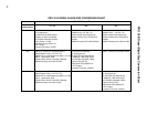
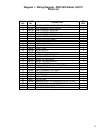
208V, 3 Ph 230V, 3 Ph 460V, 3 Ph 575V, 3 Ph 460V, 3 Ph 575V, 3 Ph
DBI Drive Motor PN 167042 001325 001325 161461 183360 183335
Rated Horsepower 20 20 20 20 30 30
Motor Full Load Current 60 A 52 A 26 A 20.6 A 37 A 29.6 A
Motor Connections
DBI Overload Heater PN 176949 176948 176947 176946 183361 183337
Vendor PN SFH83 SFH82 SFH75 SFH72 SFH78 SFH76
Power Cord PN 183433 183433 183402 183402 176957 183402
Cord Description 4 Cond, 4 GA 4 Cond, 4 GA 4 Cond, 8 GA 4 Cond, 8 GA 4 Cond, 6 GA 4 Cond, 8 GA
DBI Power Connector PN 176931 176931 176942 176944 183403 176944
Vendor PN 460C9W 460C9W 2733SW 2743SW 460C7W 2743SW
DBI Power Plug PN 176930 176930 176943 176945 183404 176945
Vendor PN 460P9W 460P9W 2731SW 2741SW 460P7W 2741SW
Current Transformer wiring *
No of primary turns 1 1 2 2 1 2
No of secondary turns -2 0 0 +6 +5 -4
H1 Side
White wire to Load Meter
Black wire to Load Meter
Red wire to motor starter
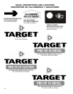
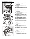
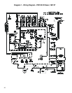
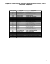
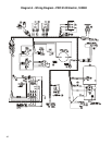
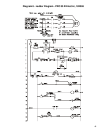
Diagram 5 - PRO 35 III Electric Wiring Instructions