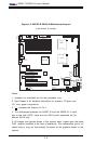
Chapter 2: Installation
2-23
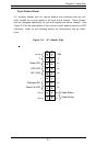
K
B
/
M
o
u
s
e
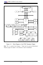
DIMM 4A
DIMM 4B
DIMM 3A
DIMM 3B
DIMM 2A
DIMM 2B
DIMM 1A
DIMM 1B
S
P
K
R
T
u
m
w
a
te
r
(N
o
rth
B
rid
g
e
)
(S
o
u
th
B
r
id
g
e
)
IDE #1
IDE #2
Floppy
F
a
n
4
USB2/3
JD2
J
F
1
FAN7
CPU1
CPU2
JD
1
J24
U
S
B
0
/1
J
L
A
N
1
CO
M
2
CO
M
1
Parrallel
Port
Fan6
Fan5
J32
4-pin
PWR
Bank 1
Bank 1
Bank 2
Bank 2
Bank 3
Bank 3
Bank 4
Bank 4
ATX PWR
J1B4
JPF
Force
PW
JLAN1
L
in
e
_
In
/
L
in
e
_
O
u
t
JPAC
SI/O
x
1
6
P
C
I E
X
P
#
6
P
C
I #
5
-3
3
M
H
z
P
C
I#
3
-3
3
M
H
z
P
C
IX
#
2
-6
6
M
H
z
J2
7
C
D
1
C
D
2
P
C
IX
#
1
-6
6
M
H
z
Z
C
R
G
L
A
N
C
T
R
L
J
W
O
R
S
M
B
u
s
J
2
2
F
a
n
3
JK
1
FAN1
J1D1
JC2
Mic
JC1
x
8
P
C
I E
X
P
#
4
J
W
O
L
JL1
J
A
R
J
O
H
1
J
P
1
5
JP12
M
a
rv
e
ll
FAN2
JWD
SATA0
SATA1 SATA0
SATA1
SATA2
M
a
rv
e
ll's
SATA3
S
A
T
A
A
C
T
L
E
D
B
a
tte
r
y
SATAI
2
C
JPS1
F
a
n
8
BIOS
J
P
L
1
J
B
T
1
6041
6300ESB
JP13
In
te
l's
D
S
1
D
S
9
D
S
2
D
S
1
0
D
S
3
D
S
1
1
D
S
4
D
S
1
2
J40
J23
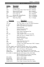
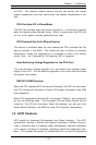
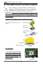
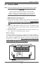
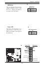
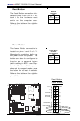
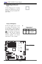
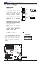
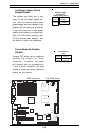
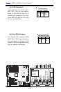
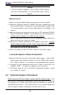
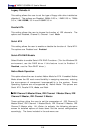
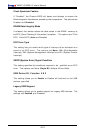
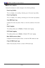
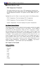
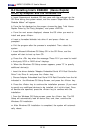
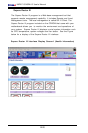
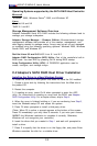
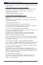
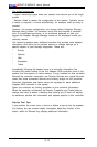
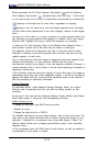
Jumper
Position
Pins 1-2
Pins 2-3
Open
Definition
WD to Reset
WD to NMI
Disabled
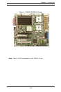
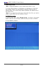
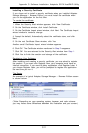
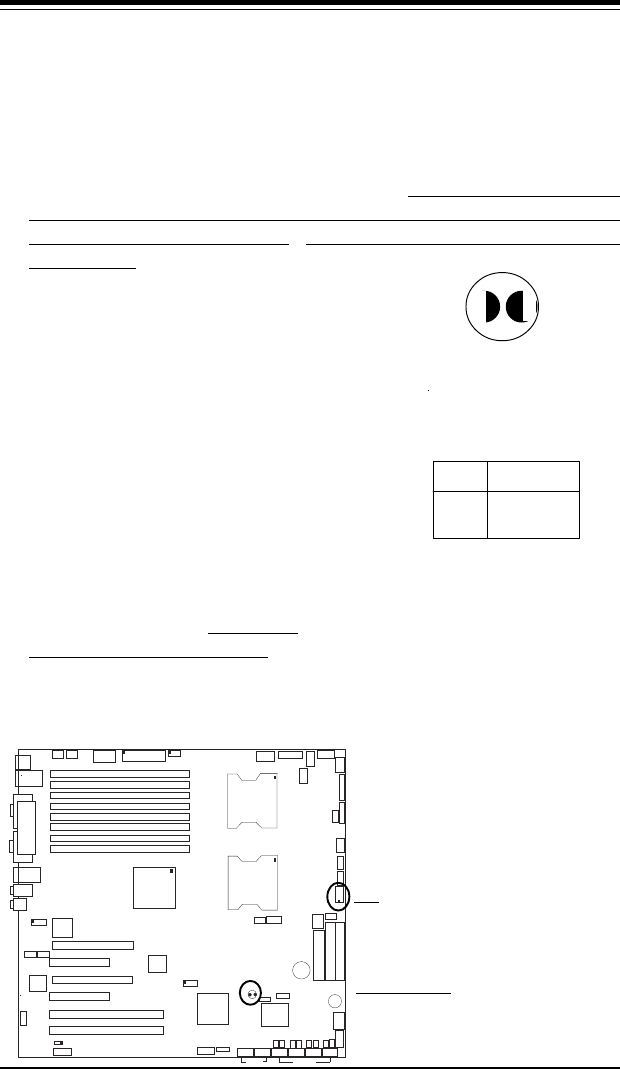
Watch Dog
Jumper Settings (JWD)
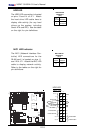
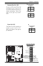
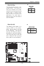
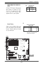
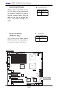
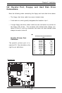
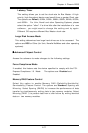
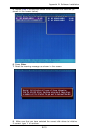
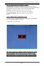
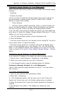
CMOS Clear
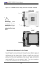
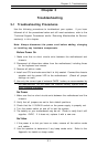
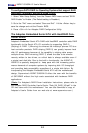
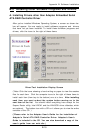
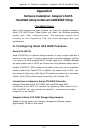
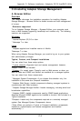
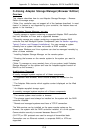
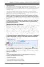
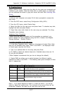
JBT1 is used to clear CMOS. Instead of pins, this "jumper" consists of
contact pads to prevent the accidental clearing of CMOS. To clear CMOS,
use a metal object such as a small screwdriver to touch both pads at the
same time to short the connection. Always remove the AC power cord
from the system before clearing CMOS. Note: For an ATX power supply,
you must completely shut down the system, remove the AC power cord and
then short JBT1 to clear CMOS. Do not use the PW_ON connector to
clear CMOS.
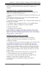
Watch Dog Enable/Disable
JWD is used to enable Watch Dog,
a system monitor that can reboot
the system when a software ap-
plication hangs. Pins 1-2 will
cause WD to reset the system if
an application hangs. Pins 2-3 will
generate a non-maskable interrupt
signal for the application that
hangs. See the table on the right
for jumper settings. Watch Dog
can also be enabled via BIOS.
Clear CMOS
WD