Chapter 2: Installation
2-25
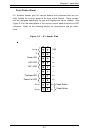
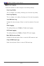
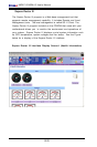
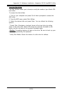
Jumper
Position
Open
Closed
Definition
Normal
Force On
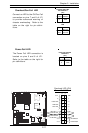
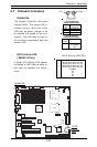
Force Power On
(JPF)
Force-Power-On Enable/
Disable
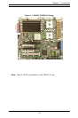
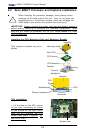
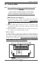
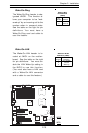
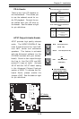
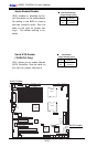
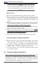
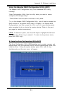
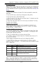
Jumper JPF allows you to enable or
disable the function of Force-
Power-On. If enabled, the power
will always stay on automatically.
If this function disabled, the user
needs to press the power button to
power on the system.
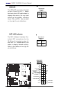
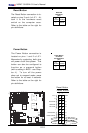
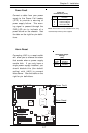
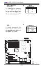
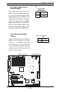
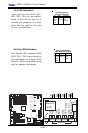
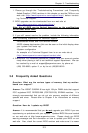
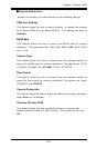
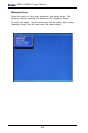
3rd Power Supply Alarm
Enable/Disable
The system can notify you in the
event of the 3rd power supply fail-
ure. Use this feature when three
power supply units are installed in the
chassis with one acting as a backup.
If you only have one or two power
supply units installed, you should dis-
able this (the default setting) with
JP13 to prevent false alarms. See
the table on right for pin definitions.
Jumper
Position
Open
Closed
Definition
Enabled
Disabled
3rd Power Supply
Alarm Enable
Jumper Settings (JP13)
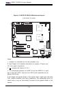
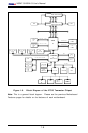
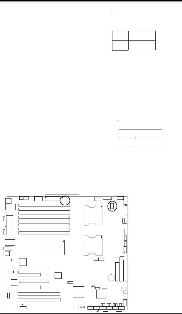
KB/
Mouse
DIMM 4A
DIMM 4B
DIMM 3A
DIMM 3B
DIMM 2A
DIMM 2B
DIMM 1A
DIMM 1B
SPKR
Tumwater
(NorthBridge)
(South
Bridge)
IDE #1
IDE #2
F
lo
ppy
Fan4
USB2/3
JD2
JF
1
FAN7
CPU1
CPU2
JD1
J24
U
S
B
0
/1
JLAN1
C
O
M
2
C
O
M
1
Parrallel
Port
Fan6
Fan5
J32
4-pin
PWR
Bank 1
Bank 1
Bank 2
Bank 2
Bank 3
Bank 3
Bank 4
Bank 4
ATX PWR
J1B4
JPF
Force
PW
JLAN
1
L
in
e
_
In
/
L
in
e
_
O
u
t
JP
A
C
SI/O
x
1
6
P
C
I E
X
P
#
6
P
C
I #
5
-3
3
M
H
z
P
C
I#
3
-3
3
M
H
z
P
C
IX
#
2
-6
6
M
H
z
J2
7
C
D
1
C
D
2
P
C
IX
#
1
-6
6
M
H
z
Z
C
R
GLAN
CTRL
JWOR
SMBus
J
2
2
Fan3
J
K
1
FAN1
J1D1
JC
2
Mic
JC
1
x
8
P
C
I E
X
P
#
4
JWOL
JL1
J
A
R
J
O
H
1
J
P
1
5
JP12
Marvell
FAN2
JWD
SATA0
SATA1 SATA0
SATA1
SATA2
Marvell's
SATA3
SATA
ACT
LED
Battery
SATAI
2
C
JPS1
F
an8
BIOS
JPL1
J
B
T
1
6041
6300ESB
JP13
Intel's
D
S
1
D
S
9
D
S
2
D
S
1
0
D
S
3
D
S
1
1
D
S
4
D
S
1
2
J40
J23
PWR Force-On
3rd PWR Alarm