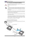
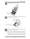
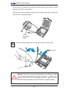
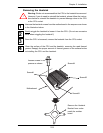
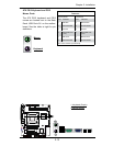
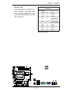
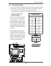
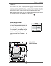
2-9 Serial ATA and HDD Connections
Note the following conditions when connecting the Serial ATA and hard disk drive
cables:
• Be sure to use the correct cable for each connector. Refer to Page 1-1 for cables
that came with your shipment.
• A red mark on a wire indicates the location of pin 1.
• The connector with twisted wires always connects to drive A, and the connector
that does not have twisted wires always connects to drive B.
A
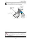
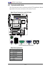
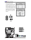
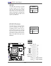
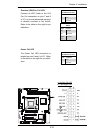
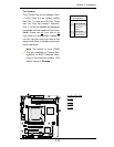
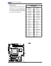
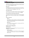
SATA Connectors
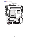
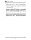
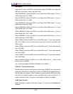
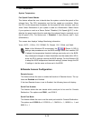
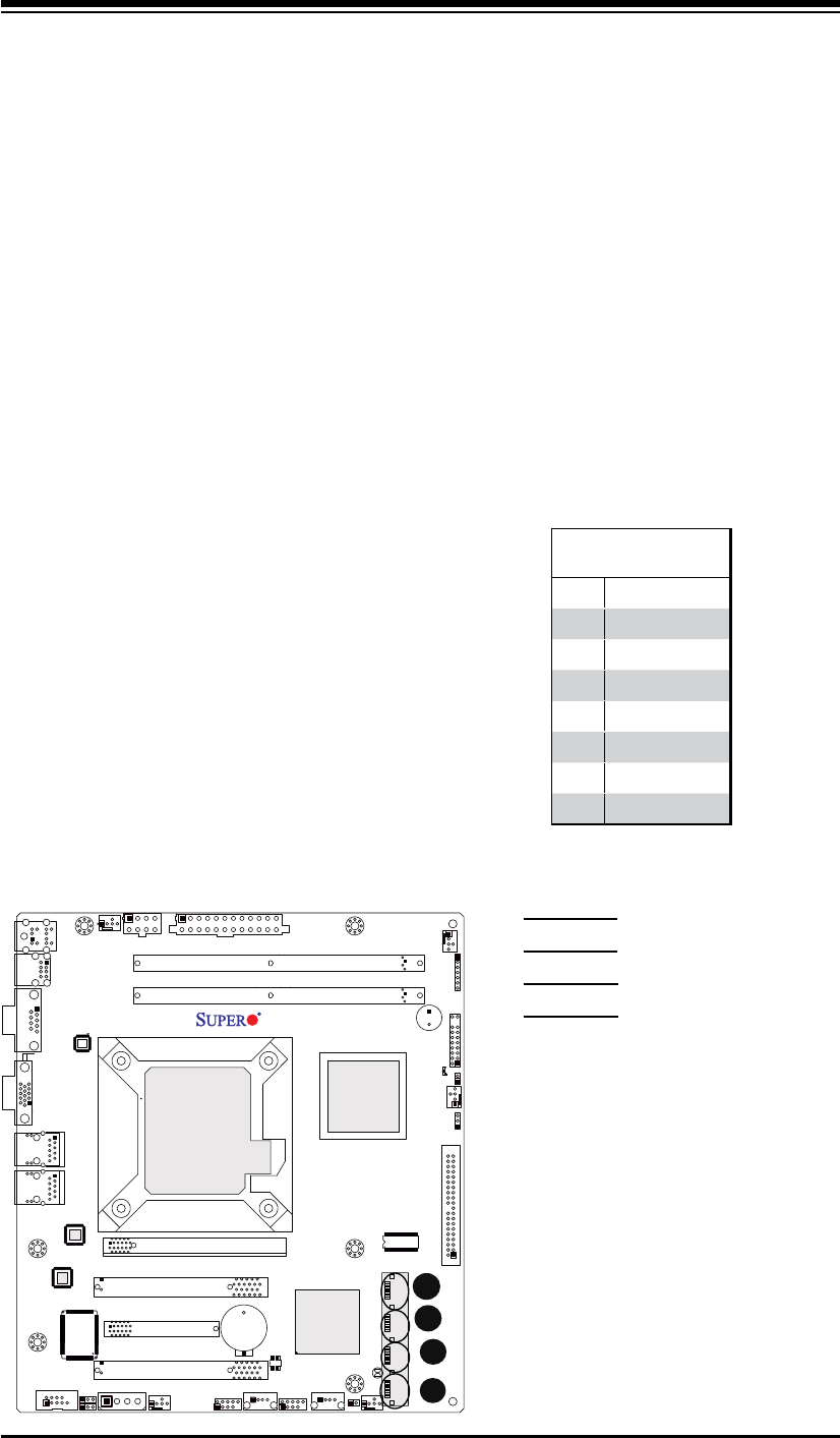
Four Serial ATA (SATA) connectors (I-SA-
TA 0~3) are located on the motherboard
to provide serial link connections. Se-
rial Link connections provide faster data
transmission than those of the traditional
Parallel ATA. These four SATA connec-
tors are supported by the Intel ICH7R
South Bridge. See the table on the right
for pin defi nitions.
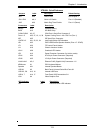
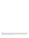
SATA Connectors
Pin Defi nitions
Pin# Signal
1 Ground
2 SATA_TXP
3 SATA_TXN
4 Ground
5 SATA_RXN
6 SATA_RXP
7 Ground
B
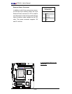
A. I-SATA0
B. I-SATA1
C. I-SATA2
D. I-SATA3
C
D