Chapter 3 PXI-8170 Series Installation
PXI-8170 Series User Manual 3-2 www.ni.com
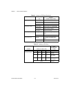
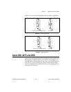
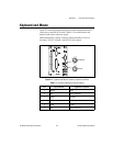
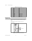
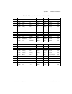
Legacy IRQ—INTP J7: 3-5 short INTP connects to NMI
J7: 1-3 short INTP connects to IRQ14
J7: 3 open INTP not connected
Legacy IRQ—INTS J7: 4-6 short INTS connects to serialized IRQ
J7: 2-4 short INTS connects to IRQ15
J7: 4 open INTS not connected
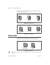
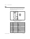
Active Keyboard Port S1: up Controller front panel keyboard
port
S1: down Chassis keyboard (if available)
Active Mouse Port S2: up Controller front panel mouse
port
S2: down Chassis mouse (if available)
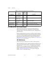
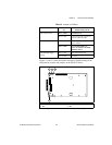
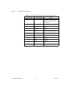
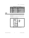
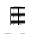
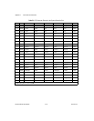
Table 3-2. Switches on CPU Board
Function Switch (X = Off, O = On)
Setting
(Default Setting
in Bold)
LCD Resolution
Mode/LCD Enable
S3: 1 S3: 2 S3: 3 S3: 4
O O O O No LCD
O X O X 640 × 480/
LCD enabled
O X X X 800
×
600/
LCD enabled
Others Reserved
Table 3-1. Jumpers on CPU Board (Continued)
Pin
Function
(Default Setting in Bold)