Index
PXI-8170 Series User Manual Index-4 www.ni.com
PXI-8170 Series
benefits of PXI, 1-3
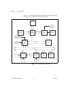
block diagram, 2-2
common questions and answers, F-1
configuring, A-1
connecting on the PXI backplane, A-3
connectors
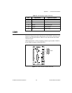
COM1 connector and signals, E-5
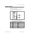
keyboard and mouse connector and
signals, E-3
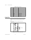
parallel port connector and
signals, E-6
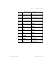
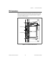
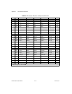
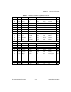
PXI connector and signals, E-9
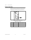
Universal Serial Bus (USB)
connector and signals, E-8
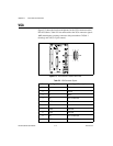
VGA connector and signals
(table), E-4
controllers, 1-1
CPU parts locator diagram, 3-4
design, 1-3
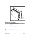
embedded computer (figure), 1-2
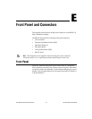
front panel
connectors, E-1
features, 1-4
thickness of, E-1
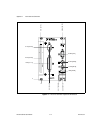
front panel layout and dimensions
(figure), E-2
functional description, 2-1
hard drive, 1-4
hardware default settings, 3-1
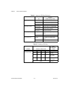
jumpers on CPU board (table), 3-1
jumpers on I/O board (table), 3-3
switches on CPU board (table), 3-2
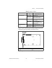
I/O board parts locator diagram, 3-3
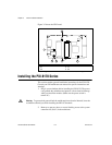
installed in a PXI mainframe (figure), 3-6
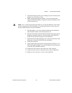
installing, 3-4
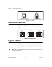
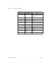
ISA interrupt resource allocation
(table), C-1
LEDs, D-1
logic blocks, 2-3
memory, 1-4
models, 1-4
monitor, F-1
National Instruments software, 1-7
overview, 1-1
peripheral expansion overview
(table), 1-5
RAM, recommendations for adding, B-2
removing from the PXI mainframe, 3-7
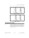
serial IRQ, INTP, and INTS, A-3
setting up, 3-7
software, 1-7
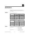
specifications, B-1
electrical, B-1
environmental, B-2
physical, B-1
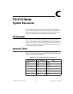
system resources, C-1
system slot functionality, 1-4
Q
questions and answers, F-1
R
RAM
See also memory
adding RAM, B-2
common questions, F-1
installed system RAM, A-1
SO-DIMMs from National Instruments
(note), B-2
type of memory in PXI-8170 Series, 1-4
resources. See system resources
resource tables, C-1
RS-232 serial, E-1
S
SCSI drive, booting from, F-2
serial IRQ, INTP, and INTS, A-3