Chapter 2: Installation
2-21
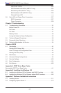
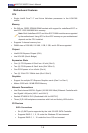
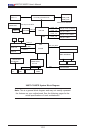
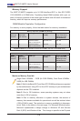
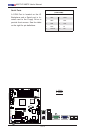
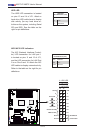
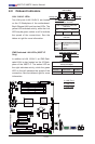
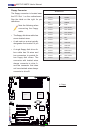
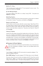
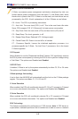
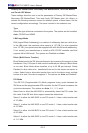
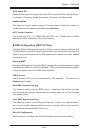
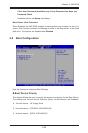
BMC JTAG
1
SAS1
SAS2
SAS7
SAS3
SAS4
SAS5
SAS6
JWOL
Battery
JD1
SPKR1
JAR
JI2C1
JI2C2
JPS2
JL1
1
JOH
1
JF1
LES1
LE1
COM1
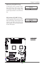
F AN 4
F AN 3
F AN 5
F AN 2
F AN 1
JPW1
SMBUS_PS1
JPW2
JPG1
JPUSB3
JBMC1
JPS1
JPUSB2
JPL1
JPL2
JLED
JWD
JPUSB1
IPMI_LAN
COM2
Floppy
I-Button
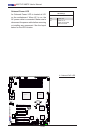
T-SGPIO1
3-SGPIO2
3-SGPIO1
USB 6/7
USB 4/5
USB3
USB2
Slot6 PCI-E 2.0 X8 on X16
Slot3 PCI-E 2.0 X8
I-SATA4
I-SATA5
Slot4 PCI-E 2.0 X4 on X8
Slot2 PCI 33MHz
Slot5 PCI-E 2.0 X8
I-SATA2
I-SATA3
DIMM1B
DIMM1A
DIMM3B
DIMM2B
DIMM2A
DIMM3A
I-SATA0
I-SATA1
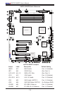
X8ST3-F/X8STE
USB 0/1
LAN2
LAN1
VGA
KB/MOUSE
BIOS
JBT1
Slot1 PCI 33MHz
SAS0
T-SGPIO2
LAN CTRL
for IPMIl LAN
LAN
CTRL1
LAN
CTRL2
SI/O
BMC CTRL
BMC
Firmware
SAS CTRL
Intel ICH10R
South Bridge
Intel X58-Express
North Bridge
Intel Processor
LES2
LSI 1068E
WPCM 450
CPU FAN
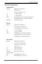
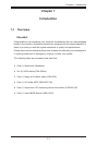
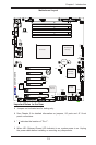
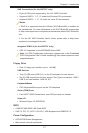
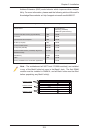
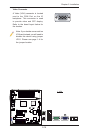
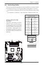
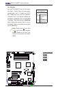
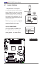
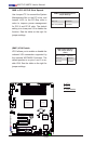
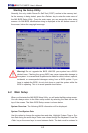
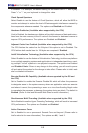
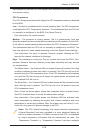
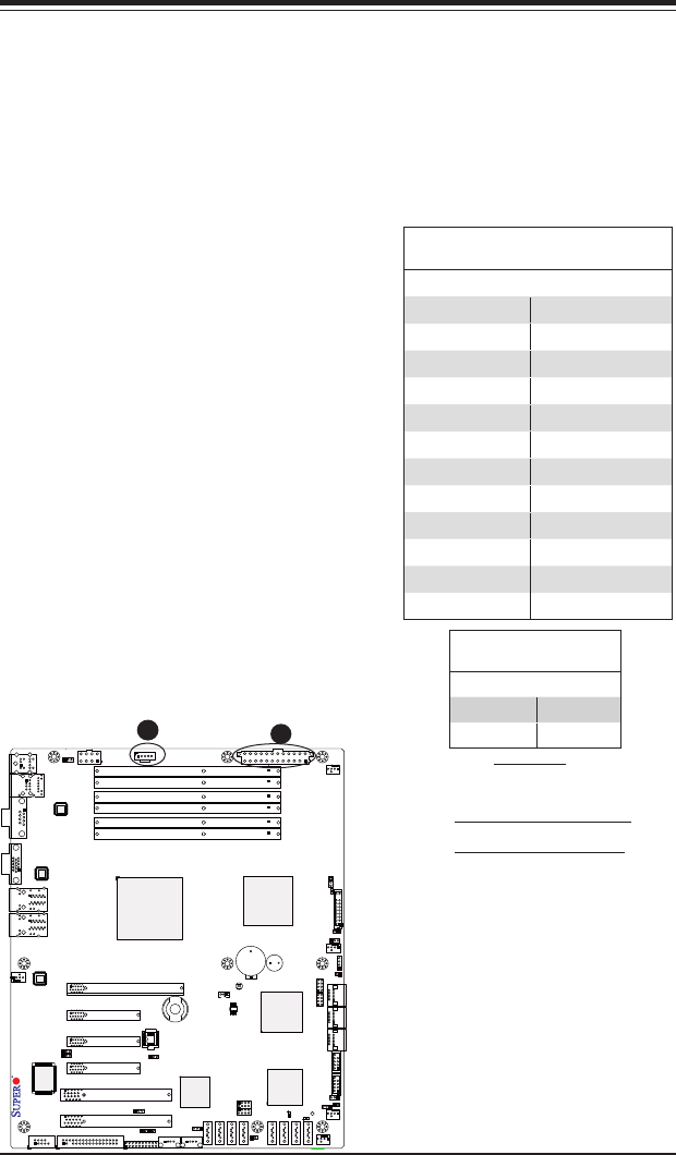
2-6 Connecting Cables
This section provides brief descriptions and pin-out denitions for onboard headers
and connectors. Be sure to use the correct cable for each header or connector.
• For information on Backpanel USB and Front Panel USB ports, refer to Page
2-14.
• For information on COM Port 1 and COM Port 2, please see Page 2-16.
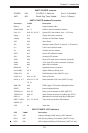
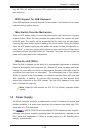
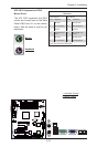
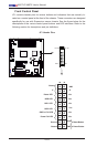
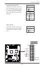
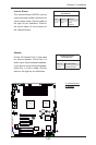
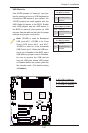
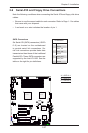
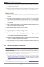
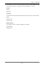
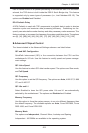
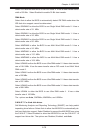
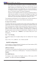
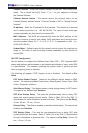
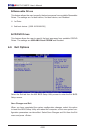
A. 24-Pin ATX Main PWR
B. 8-Pin Processor PWR
A
B
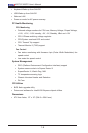
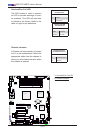
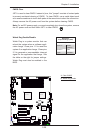
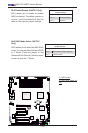
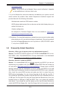
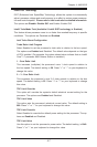
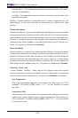
ATX Power 24-pin Connector
PinDenitions(JPW1)
Pin# Denition Pin # Denition
13 +3.3V 1 +3.3V
14 -12V 2 +3.3V
15 COM 3 COM
16 PS_ON 4 +5V
17 COM 5 COM
18 COM 6 +5V
19 COM 7 COM
20 Res (NC) 8 PWR_OK
21 +5V 9 5VSB
22 +5V 10 +12V
23 +5V 11 +12V
24 COM 12 +3.3V
(Required)
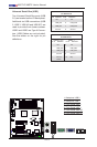
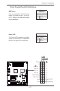
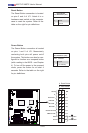
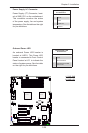
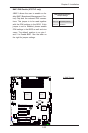
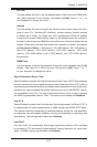
12V 8-pin Power Connec-
torPinDenitions(JPW3)
Pins Denition
1 through 4 Ground
5 through 8 +12V
ATX Main PWR & CPU PWR
Connectors
The 24-pin main power connector
(JPW1) is used to provide power to
the motherboard. The 8-pin CPU PWR
connector (JPW2) is also required for
the processor. These power connec-
tors meet the SSI EPS 12V specica-
tion. See the table on the right for pin
denitions.