2-30
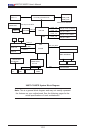
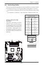
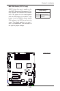
X8ST3-F/X8STE User's Manual
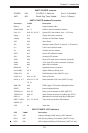
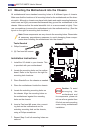
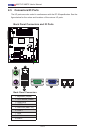
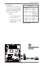
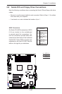
BMC JTAG
1
SAS1
SAS2
SAS7
SAS3
SAS4
SAS5
SAS6
JWOL
Battery
JD1
SPKR1
JAR
JI2C1
JI2C2
JPS2
JL1
1
JOH
1
JF1
LES1
LE1
COM1
FAN 4
FAN 3
FAN 5
FAN 2
FAN 1
JPW1
SMBUS_PS1
JPW2
JPG1
JPUSB3
JBMC1
JPS1
JPUSB2
JPL1
JPL2
JLED
JWD
JPUSB1
IPMI_LAN
COM2
Floppy
I-Button
T-SGPIO1
3-SGPIO2
3-SGPIO1
USB 6/7
USB 4/5
USB3
USB2
Slot6 PCI-E 2.0 X8 on X16
Slot3 PCI-E 2.0 X8
I-SATA4
I-SATA5
Slot4 PCI-E 2.0 X4 on X8
Slot2 PCI 33MHz
Slot5 PCI-E 2.0 X8
I-SATA2
I-SATA3
DIMM1B
DIMM1A
DIMM3B
DIMM2B
DIMM2A
DIMM3A
I-SATA0
I-SATA1
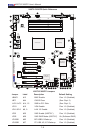
X8ST3-F/X8STE
USB 0/1
LAN2
LAN1
VGA
KB/MOUSE
BIOS
JBT1
Slot1 PCI 33MHz
SAS0
T-SGPIO2
LAN CTRL
for IPMIl LAN
LAN
CTRL1
LAN
CTRL2
SI/O
BMC CTRL
BMC
Firmware
SAS CTRL
Intel ICH10R
South Bridge
Intel X58-Express
North Bridge
Intel Processor
LES2
LSI 1068E
WPCM 450
CPU FAN
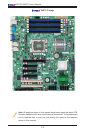
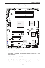
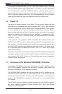
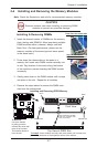
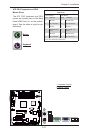
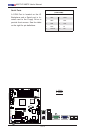
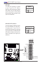
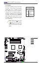
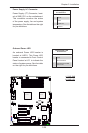
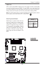
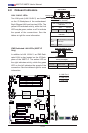
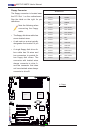
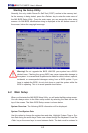
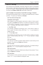
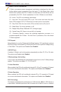
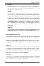
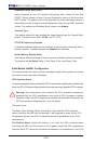
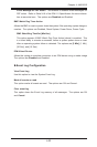
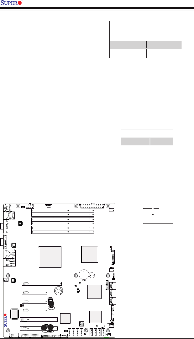
SMB to PCI-X/PCI-E Slots Speeds
Use Jumper JI
2
C1 to connect the System
Management Bus to the PCI slots, and
Jumper JI
2
C2, to the PCI-Exp. slots in
order to improve power management
for PCI-X and PCI-E slots. The default
setting is to close pins 2-3 to disable the
function. See the table on the right for
jumper settings.
SMBus to PCI-X/PCI-Exp Slots
Jumper Settings
Jumper Setting Denition
Pins 1-2 Enabled
Pins 2-3 (Default) Disabled
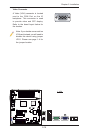
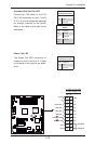
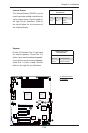
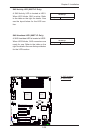
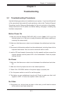
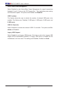
A
B
A. JI
2
C1
B. JI
2
C2
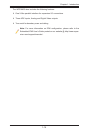
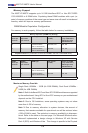
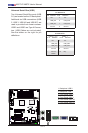
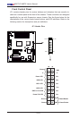
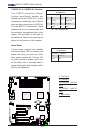
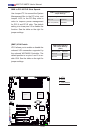
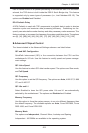
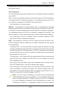
C. VGA Enable
C
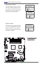
(BMC) VGA Enable/Dis-
able Jumper Settings
(JPG1)
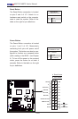
Both Jumpers Denition
Pins 1-2 Enabled
Pins 2-3 Disabled
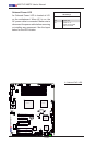
(BMC) VGA Enable
JPG1 allows you to enable or disable the
onboard VGA connection supported by
the onboard WPCM450 Controller. The
default position is on pins 1 and 2 to en-
able VGA. See the table on the right for
jumper settings.